Operation of the Device

Principle of operation

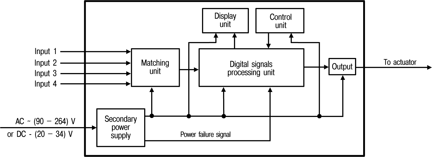
Functional diagram of the Device is shown in Figure.

Graphic
Functional diagram

The Device has four independent digital inputs for external control signals. You can connect to the inputs:

  • switching devices (buttons, switches, reed switches, relays, etc.);

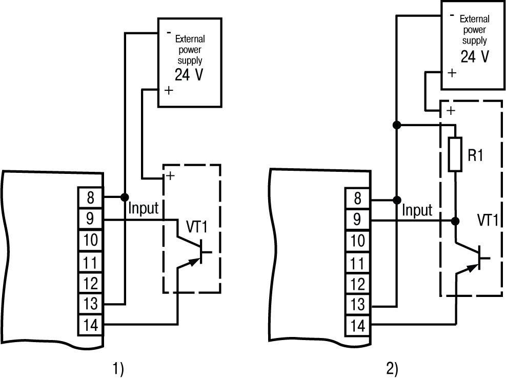
  • sensors with output n-p-n-transistor with an open collector;

  • sensors with output p-n-p-transistor.

The levels of the input signals are converted and processed in the matching unit and then sent to the digital signal processing unit that performs:

  • filtering of input signals;

  • counting pulses applied to the device inputs;

  • conversion of the value from the counter into real physical value;

  • comparing signal value to the setpoint before displaying;

  • generation of signals for controlling the outputs according to a specified algorithm.

Control unit includes buttons for entering parameters of the device.

Display unit displays the measurement results or operating parameters on the indicators and shows the counter status using LEDs.

Internal power supply converts the supply voltage for all units of the device and generates a signal indicating the loss of supply voltage.

Control and indication

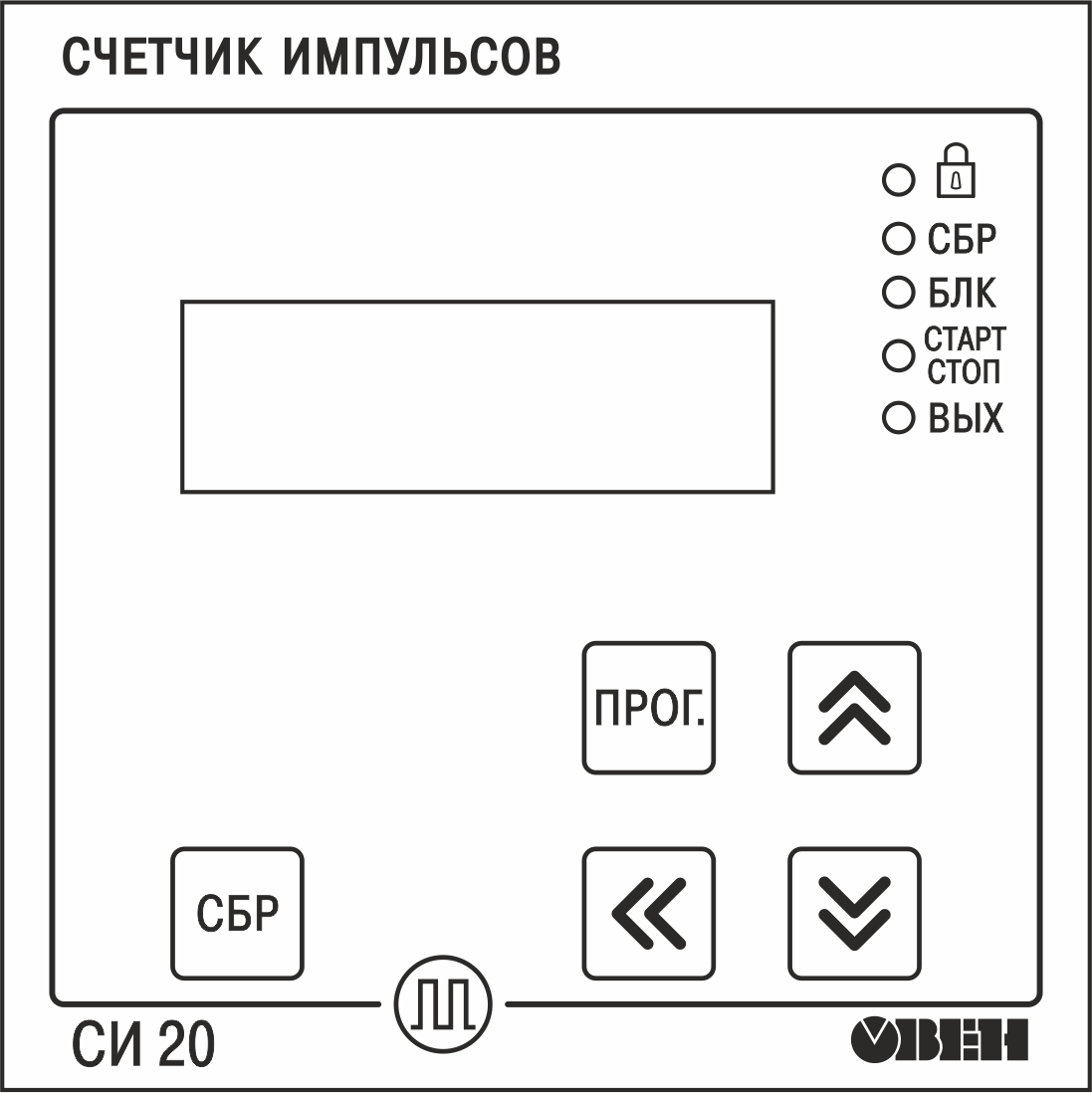
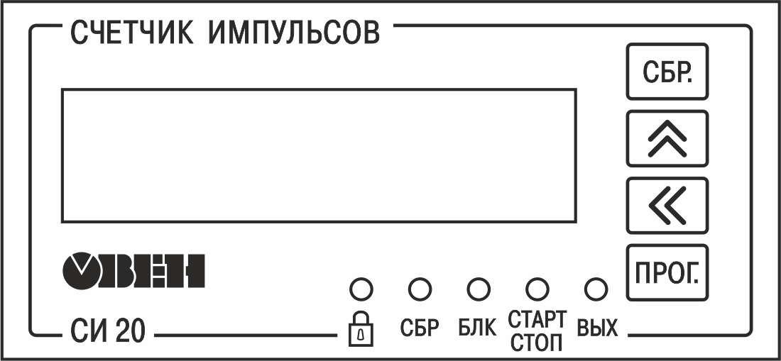
Elements of indication and control are located on the front panel of the device (see Figures and):

  • seven-segment six-digit digital indicator;
  • five LEDs;
  • four/five buttons (depending on the type of housing).
Graphic
Front panel of the device in housings for wall-mounting H and panel-mounting Щ1
Graphic
Front panel of the device in housing forpanel-mounting Щ2
Digital indicator
Operating modeDisplayed information
OperationCurrent counter value
SetupName and value of the selected parameter or setpoint value (see Appendix A)
LED States
LEDStatusValue
Graphic LightsKey lock is on
СБР LightsInput Reset is enabled
БЛК LightsInput Lock is enabled
СТАРТ/СТОПLightsCurrent device operation mode (pulse counting or stop)
ВЫХ Lights Output enabled
Buttons
ButtonOperating modeFunction
GraphicOperation
  • Reset counting register and device readings.
  • Return to the current saved setpoint value during editing process
SetupReturning the value of the parameter before changing it during the editing process
Graphic

Graphic

OperationChange the values of setpoint
SetupView parameter values and edit them
Notice
Graphic is not available on the housing Щ2.

GraphicOperationSelect editable digit when changing parameter value (used with buttons Graphic and Graphic)
Setup
Graphic

Operation

View and change the setpoint value (if the setpoint value is not locked)
Setup
  • Enter and exit the settings group
  • Enter and exit the parameter editing mode
  • Save the new parameter value in non-volatile memory of the device

Switch on and operation

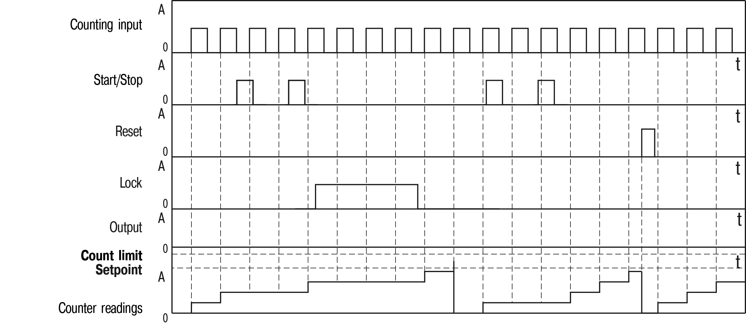
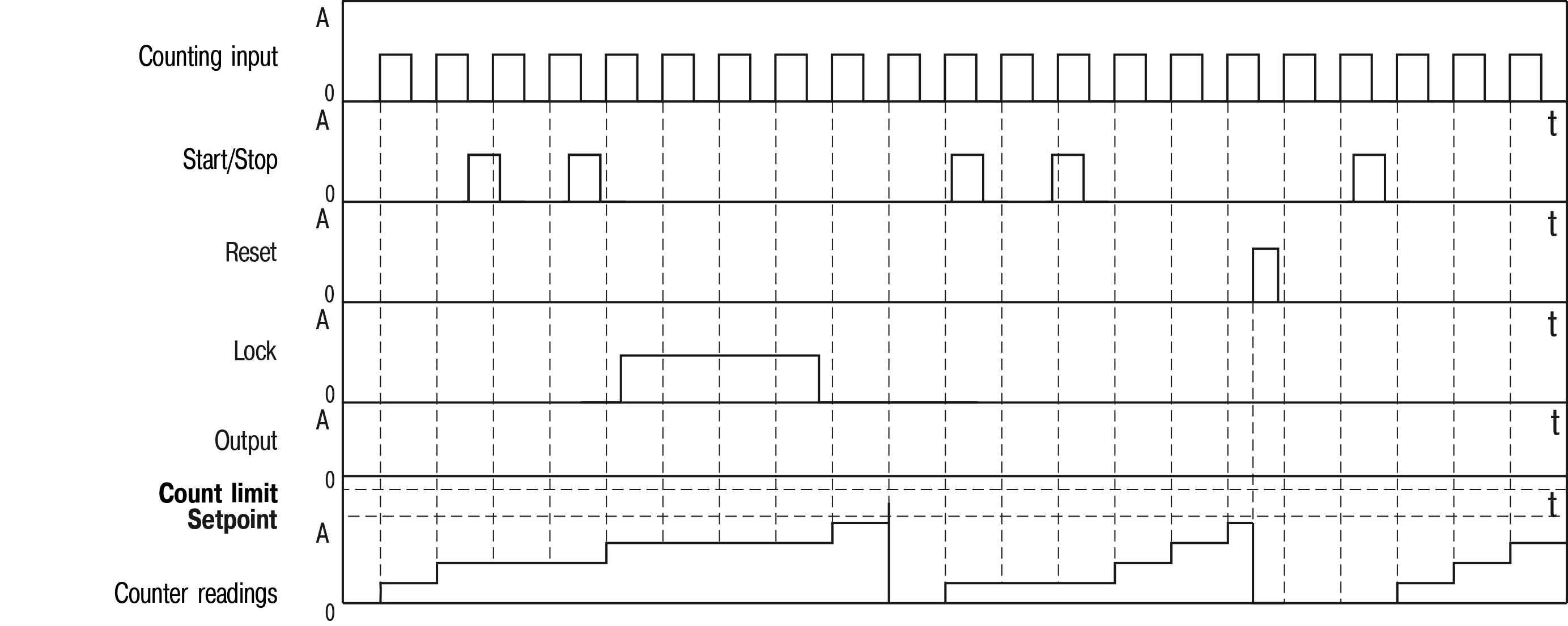
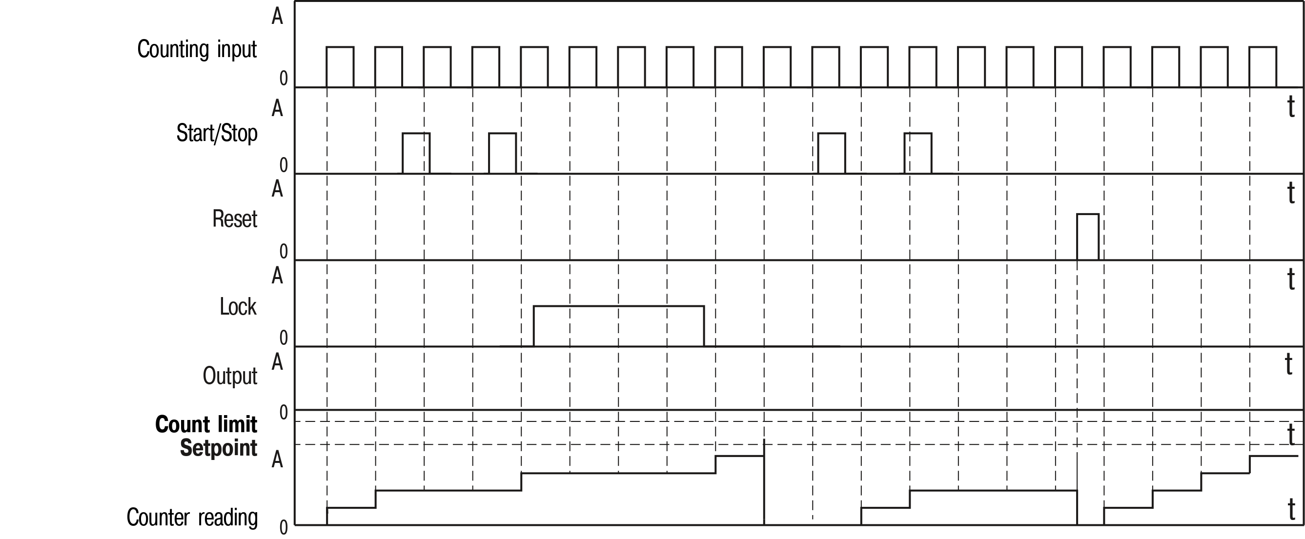
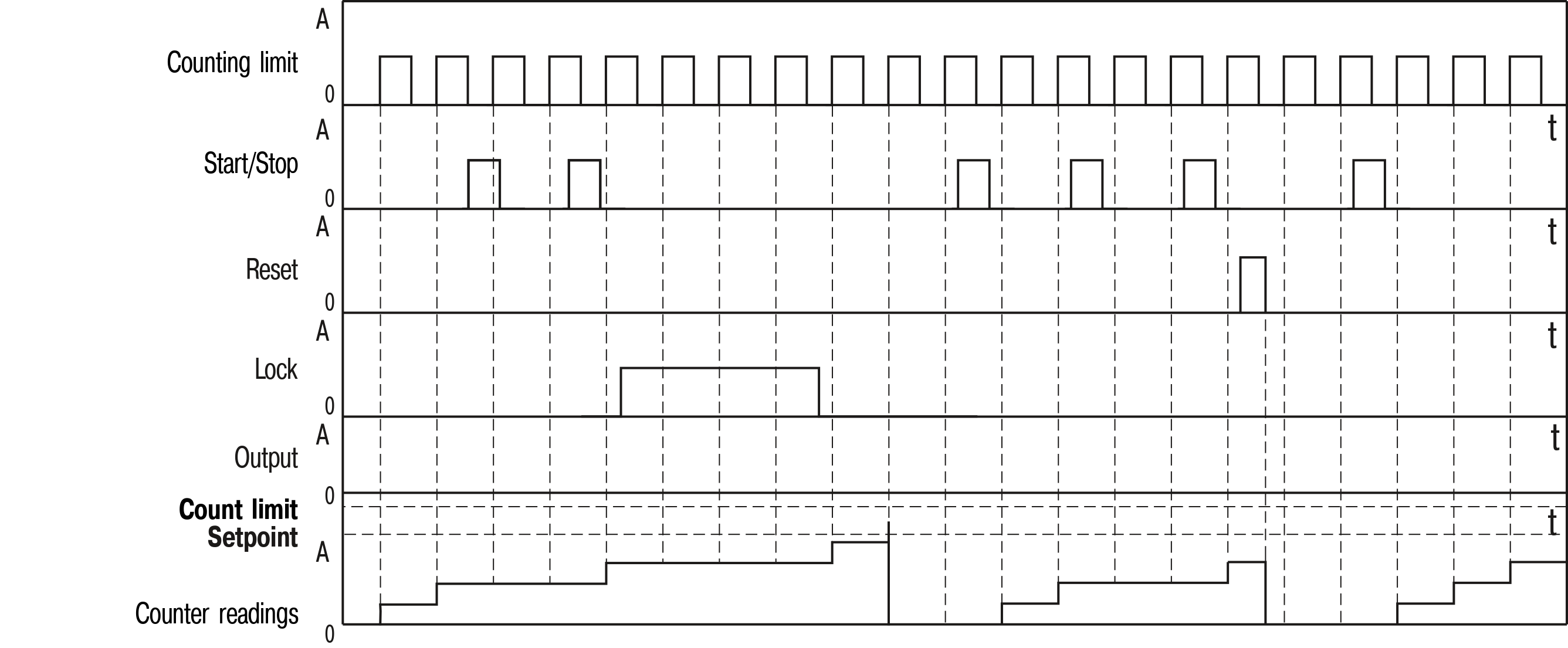
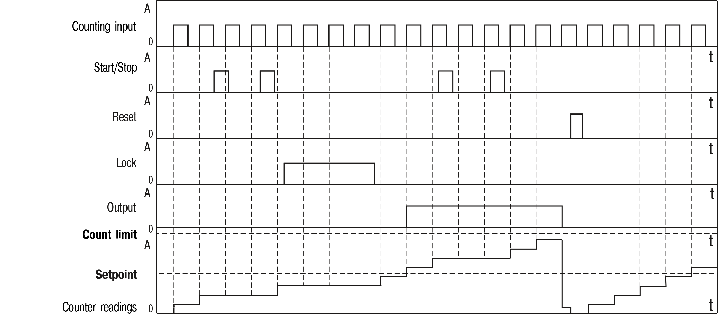
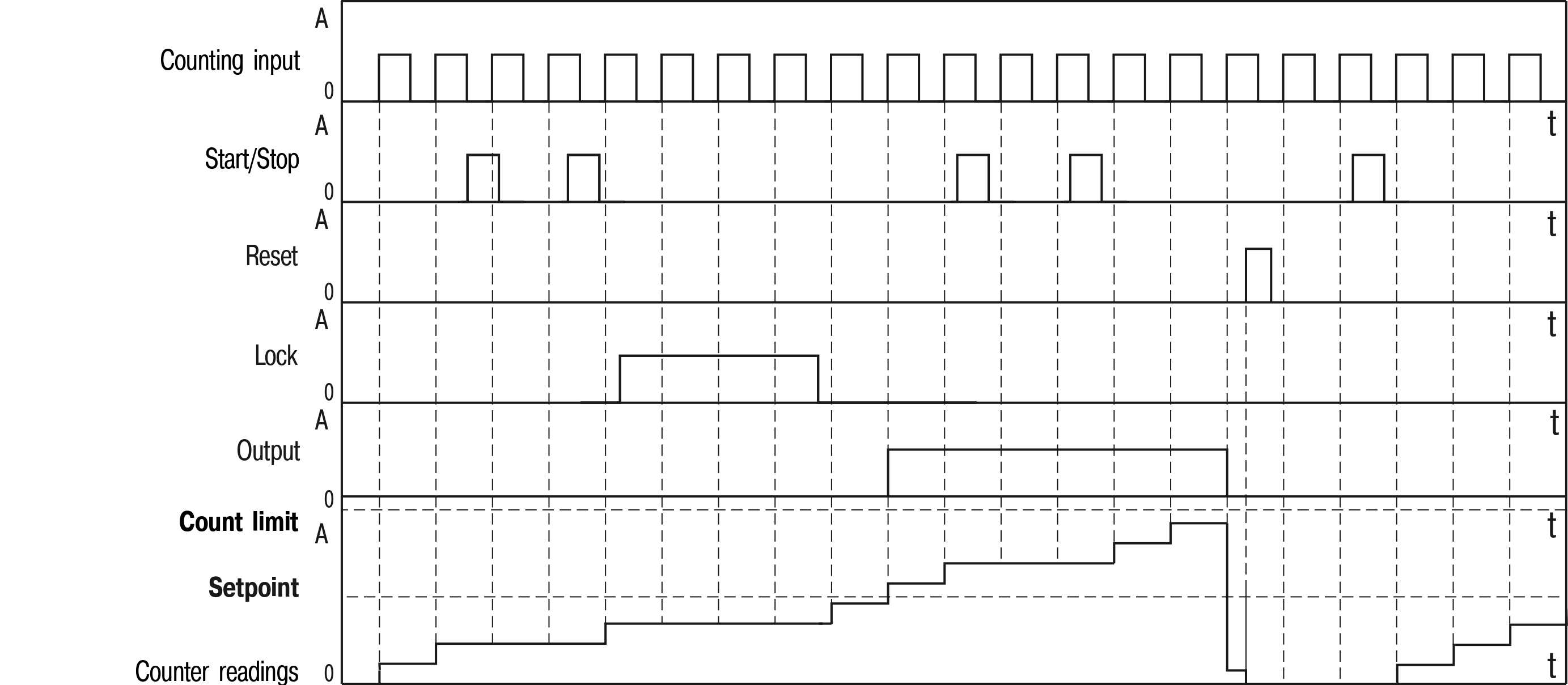
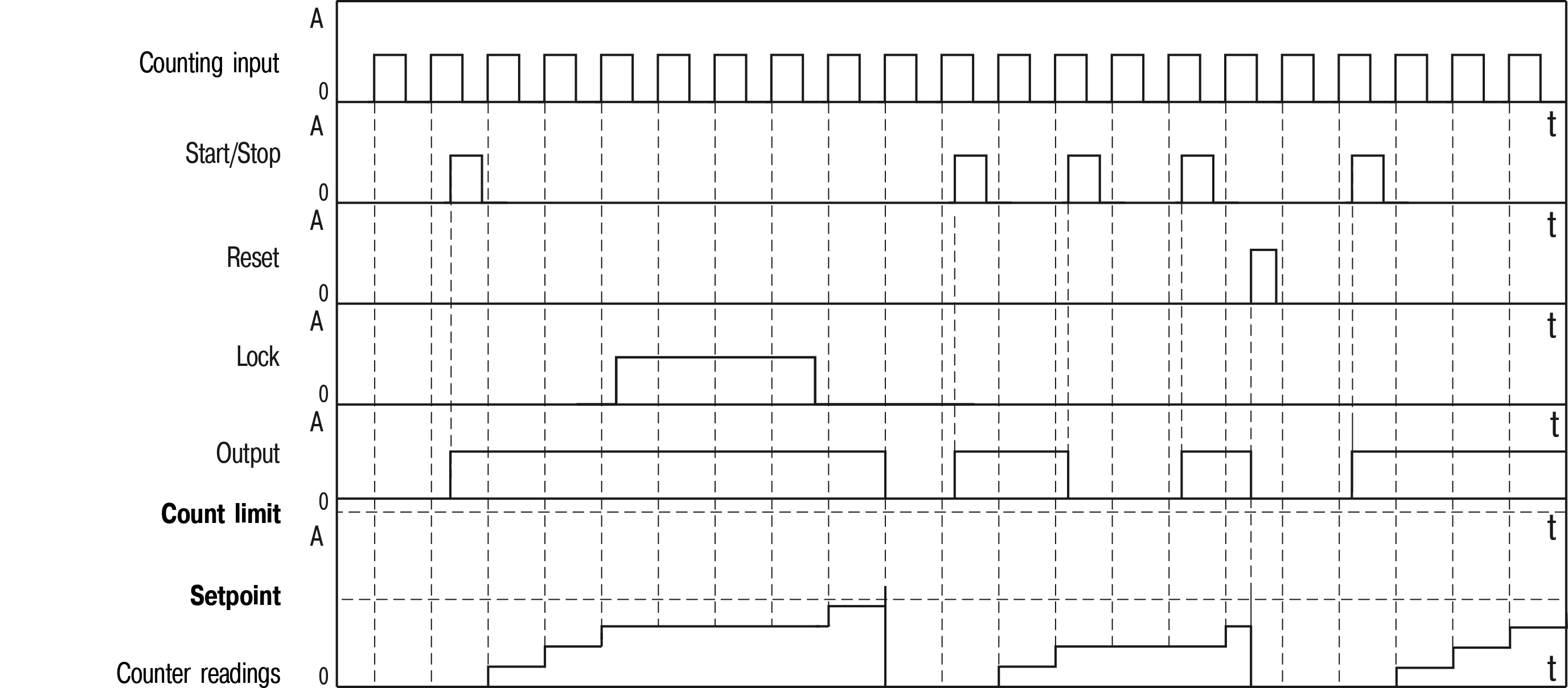
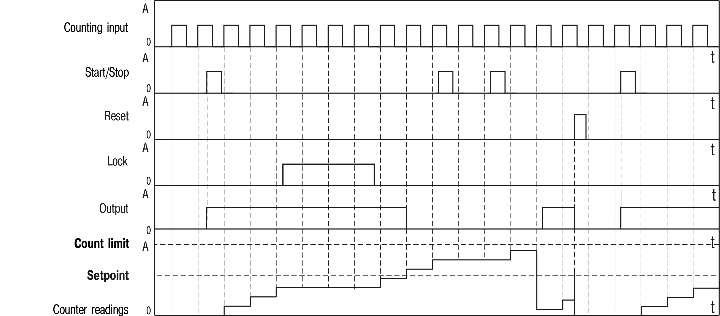
During operation (see Figure), the Device counts the number of pulses arriving at its counting input (input 1), converts this quantity into a physical value, and displays the value on the indicator.

The counter of the Device operates in the mode of direct counting (counting of pulses from zero upward). If the maximum counting value (999999) is exceeded, the number of counted pulses is reset and the counter continues counting.

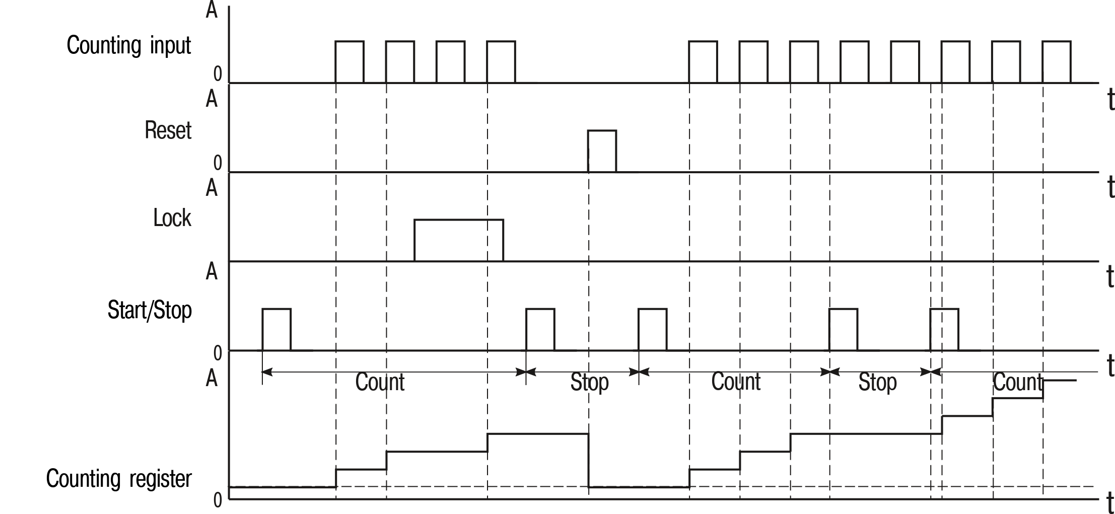
The logic of the counter on the start/stop signal (input 2) is as follows:

  • the first impulse (starting) comes to this input and enables the counting;

  • when the next (stop) pulse arrives, the counting stops.

If there is an active Reset signal (input 3), the number of counted pulses is reset.

Block (input 4) prevents the transmission of the counting pulses to the Device input. While this signal is active, counting is blocked.

Danger
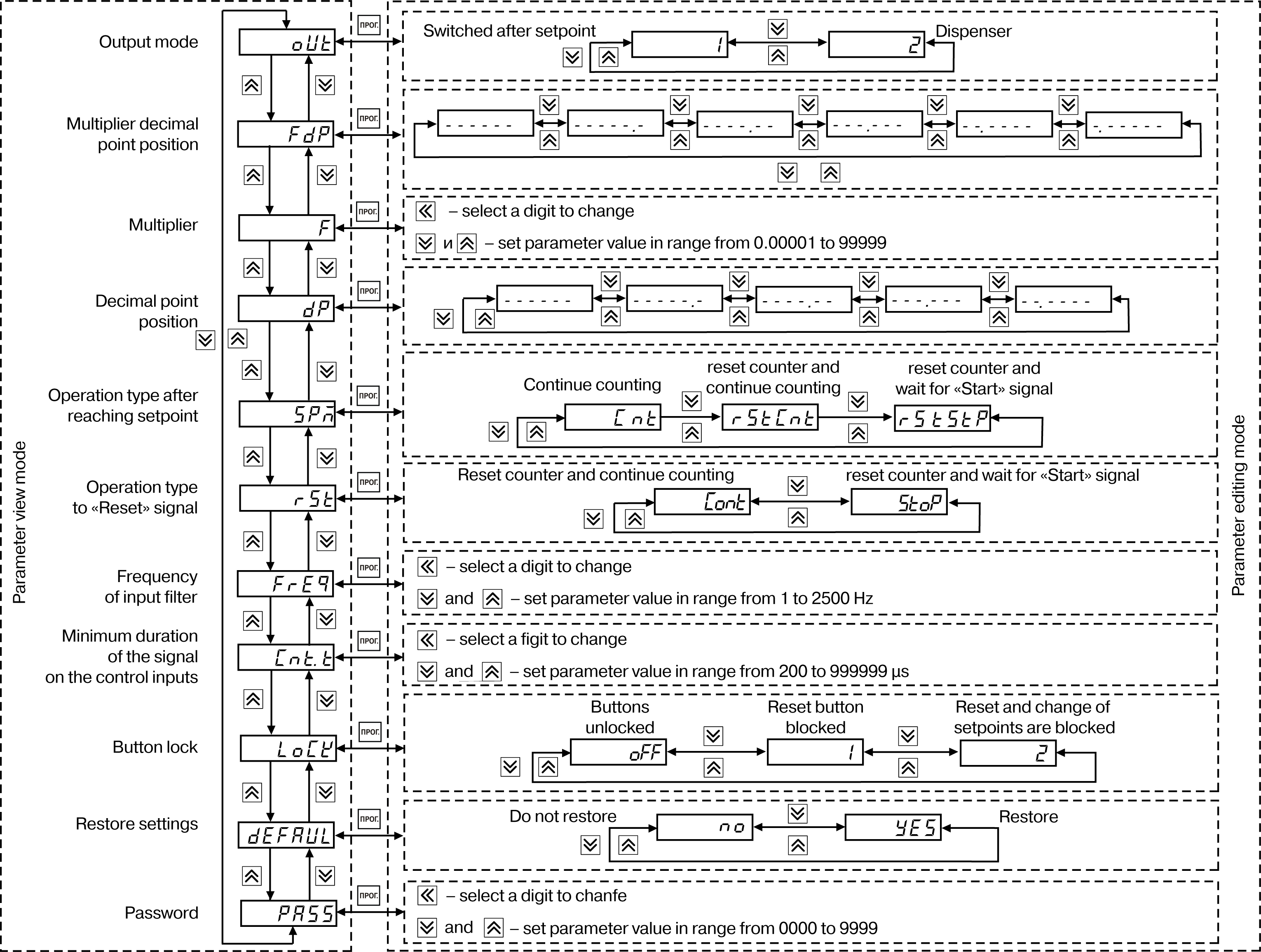
The setpoint is specified with the same accuracy as for counting physical values. The multiplier can be set from 0.00001 to 99999. The conversion of counting results (result of multiplying) will be rounded up.

The counter also filters the input signals with two filters. The first one filters the signal on the counting input by pulse duration (from 1 to 2500 Hz), the second filters signal on the control inputs of the Device (from 200 to 999999 μs).

Graphic
Device operation diagram