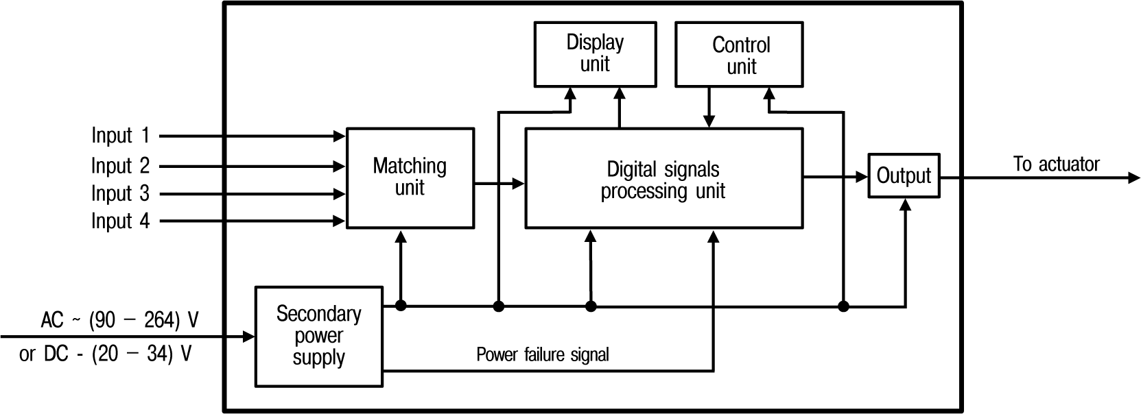
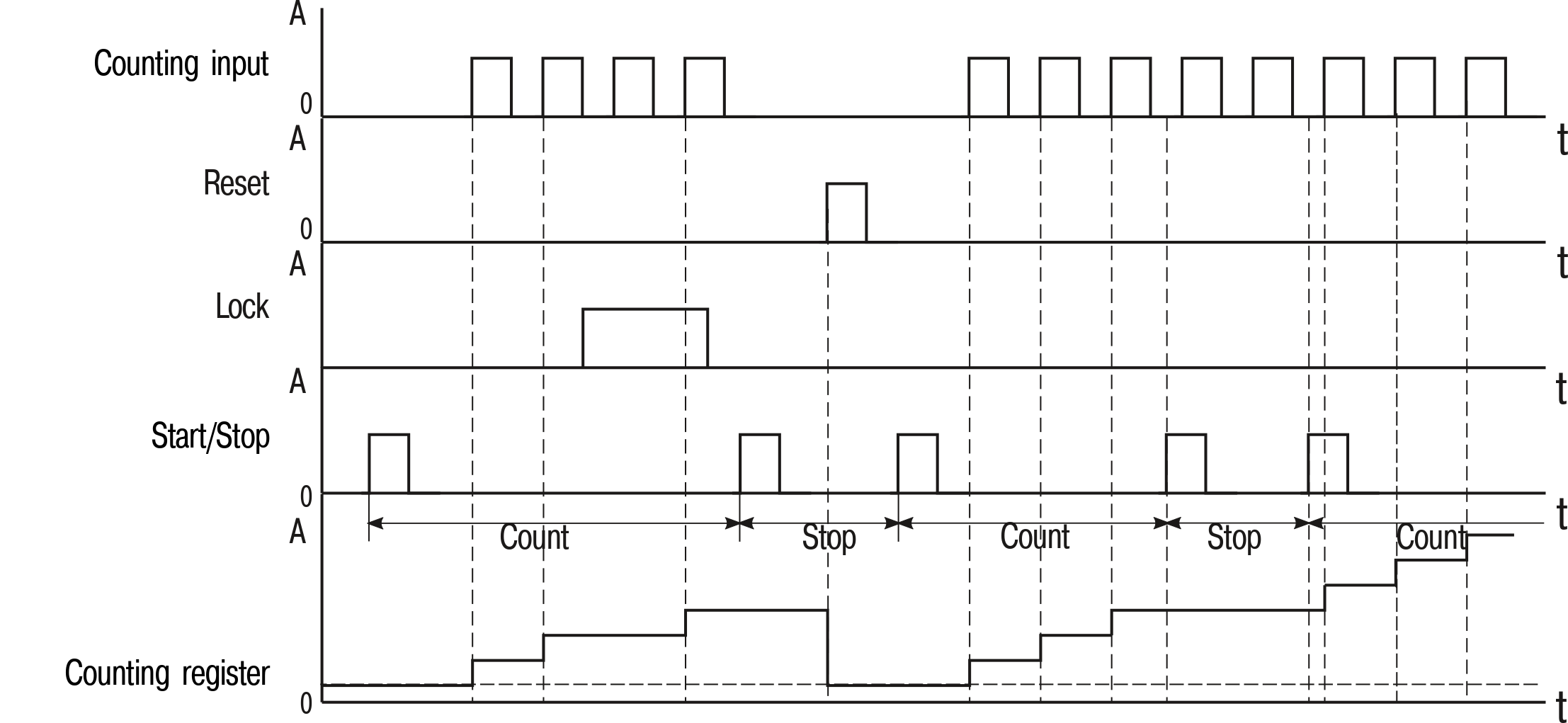
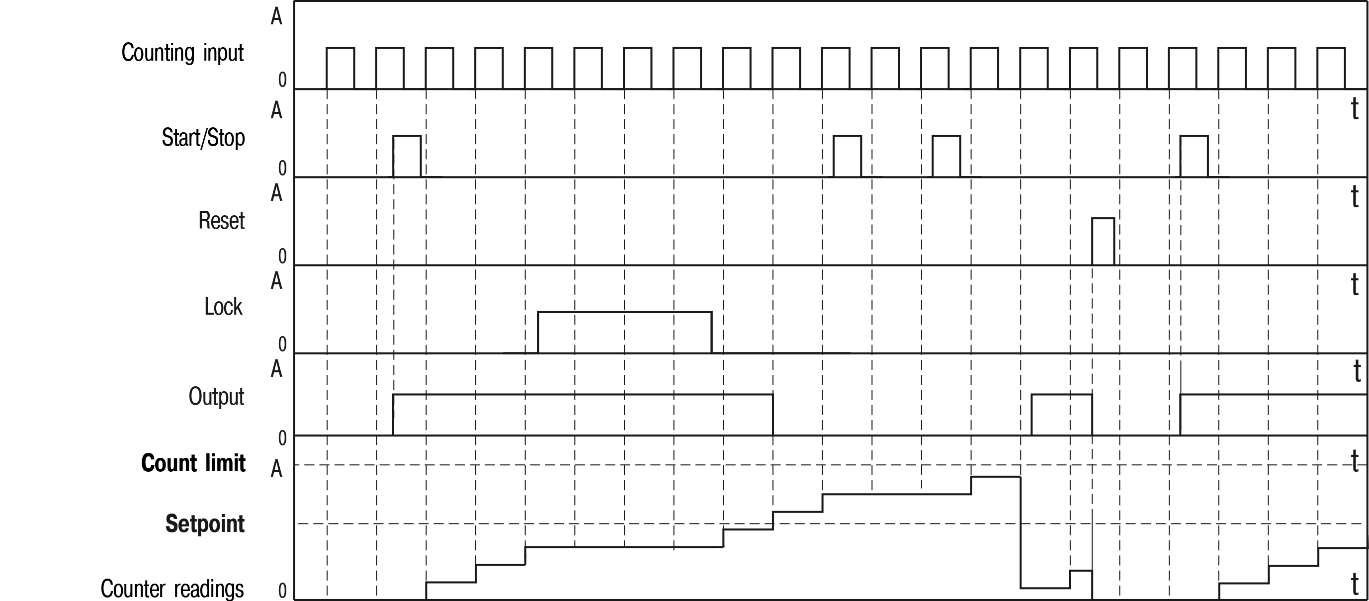
This document provides detailed information about the operation principle, design, configuration, installation and maintenance of the pulse counter СИ20, hereinafter referred to as Device.
Connection, setup and maintenance should be made only by qualified specialists after reading this manual.
The device is produced in various modifications, that are encrypted in code of full conventional designation.
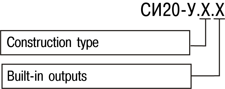
Construction type:
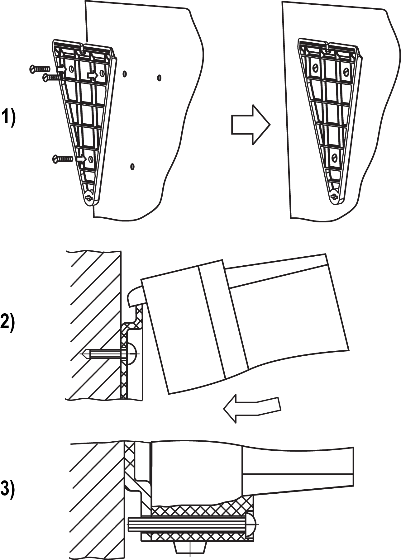
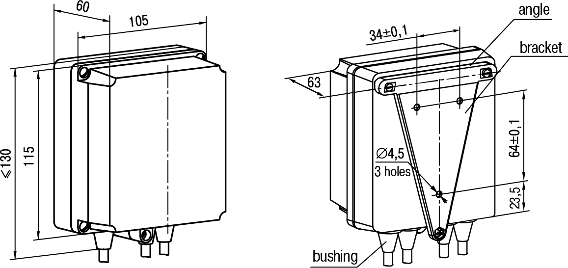
- H – wall-mounting housing;
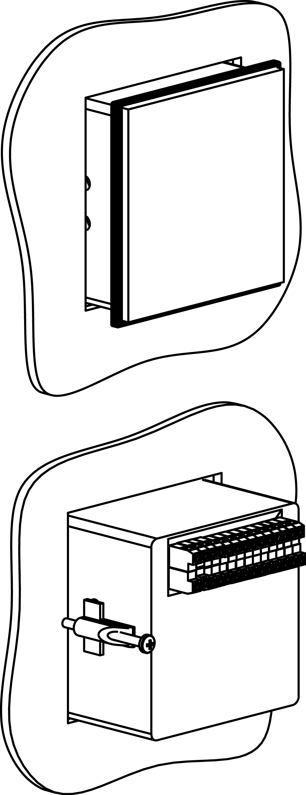
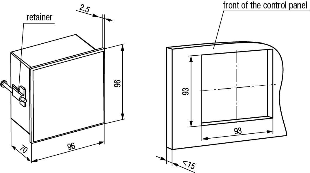
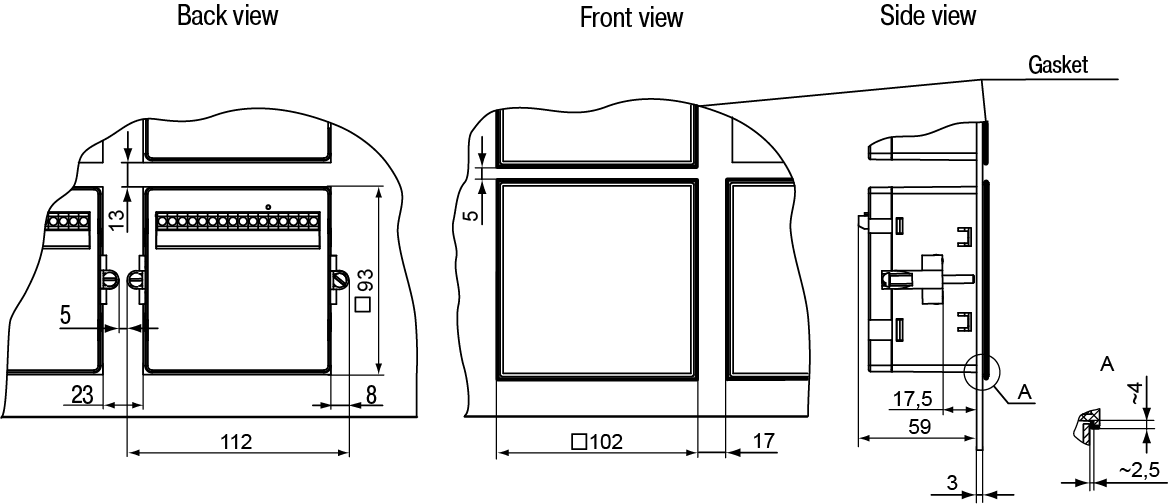
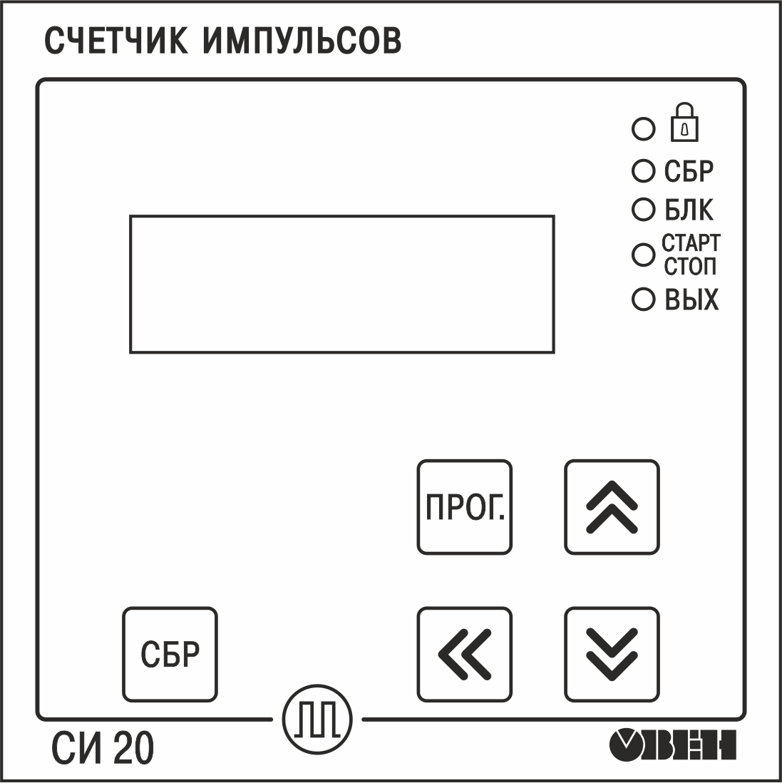
- Щ1 – panel-mounting housing (square front panel, 96x96 mm);
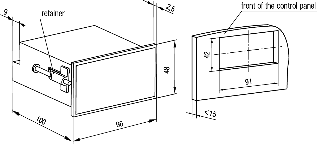
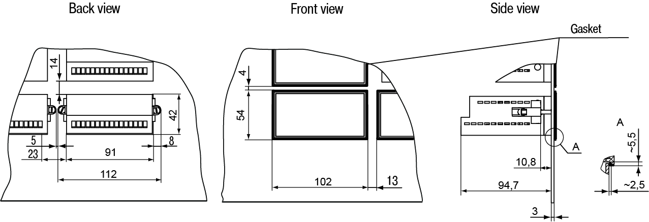
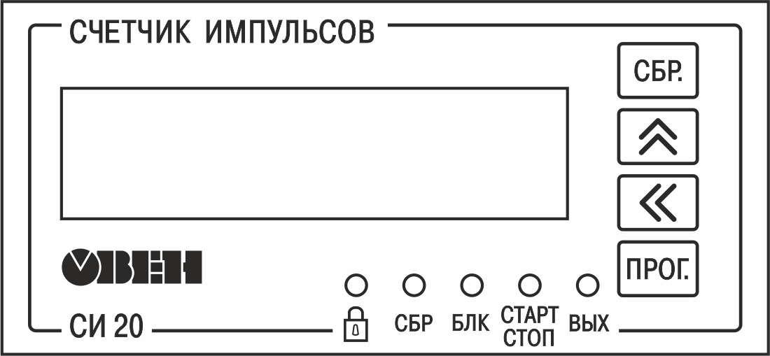
- Щ2– panel-mounting housing (rectangular front panel, 96x48 mm).
Built-in outputs:
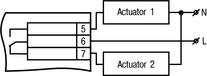
- P – electromagnetic relay;
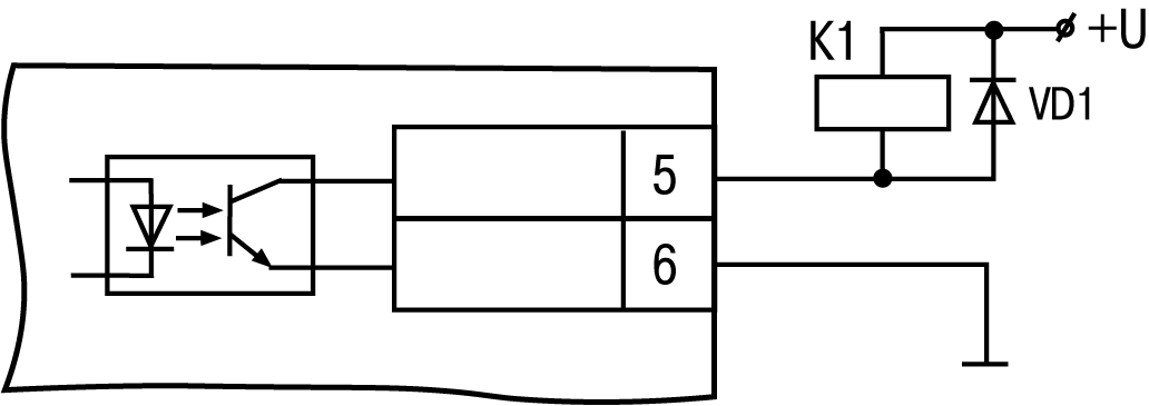
- K – transistor optocoupler of n-p-n type;
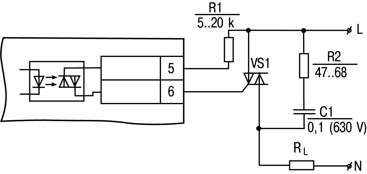
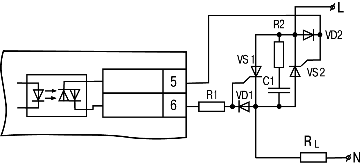
- C – triac optocoupler.
The example of designation used for ordering and in other products documentation:
Pulse counter СИ20-У.Щ1.Р ТУ 4278-009-46526536-2012.