Wiring recommendations
To ensure the reliability of electrical connections it is recommended to use copper stranded cables, the ends of which should be carefully cleaned and tinned. Otherwise use cable lugs before connection. Cable conductors should be stripped so that their bare ends do not protrude beyond the terminal strip after connecting to the device. The cable cross section must be not more than 1 mm2.
General requirements for connection lines:
-
During the cabling, communication lines that connect the Device with sensors must be isolated to a separate circuit (or several circuits) and placed separately from power cables or other sources of high-frequency and impulse interferences;
-
To protect the Device inputs from the effects of industrial electromagnetic interference, the communication lines between Device and sensors should be shielded. Special cables with shielding or grounded steel pipes of suitable diameter can be used. The cable shielding should be connected to the functional ground terminal (FE) in the control panel;
-
Network interference filters should be installed in the power supply lines;
-
Spark-fighting filters should be installed in the switching lines of power equipment.
When installing the system in which the Device operates, you should follow the rules for effective grounding:
-
all grounding lines must be laid in Y-connected circuit, ensuring good contact with the grounding element;
-
all earthing circuits must be made with wires of the largest possible cross-section;
-
it is forbidden to connect the device terminal "Common" with grounding lines.
Getting Started
If the device was kept for a long time at a temperature below minus 20 °С, then before turning it on and starting work, it should be kept in a room with a temperature corresponding to the operating range for 30 minutes.
To connect the device:
Connect the Device to a power source.
 DangerBefore applying power to the Device, check that the supply voltage and its level are correct.
- Connect primary transducers to the device inputs.
- Apply power to the device.
- Set up the device.
- Make a test run of the device algorithm to verify that the settings are correct.
- Power off the device.
- Connect operating mechanisms to the device outputs.
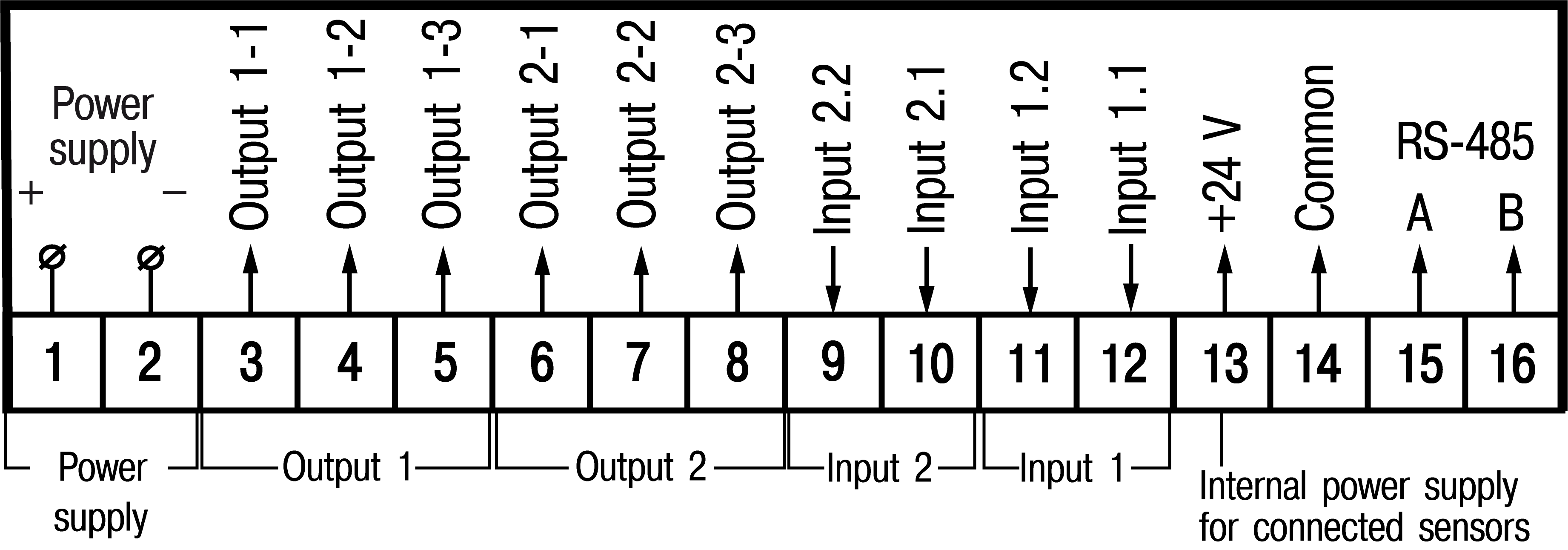
Terminal block contacts assignments
Screw terminals are located on the back wall (panel-mounting) or inside the device (wall-mounting). The terminal block contacts assignment is shown in Figure.
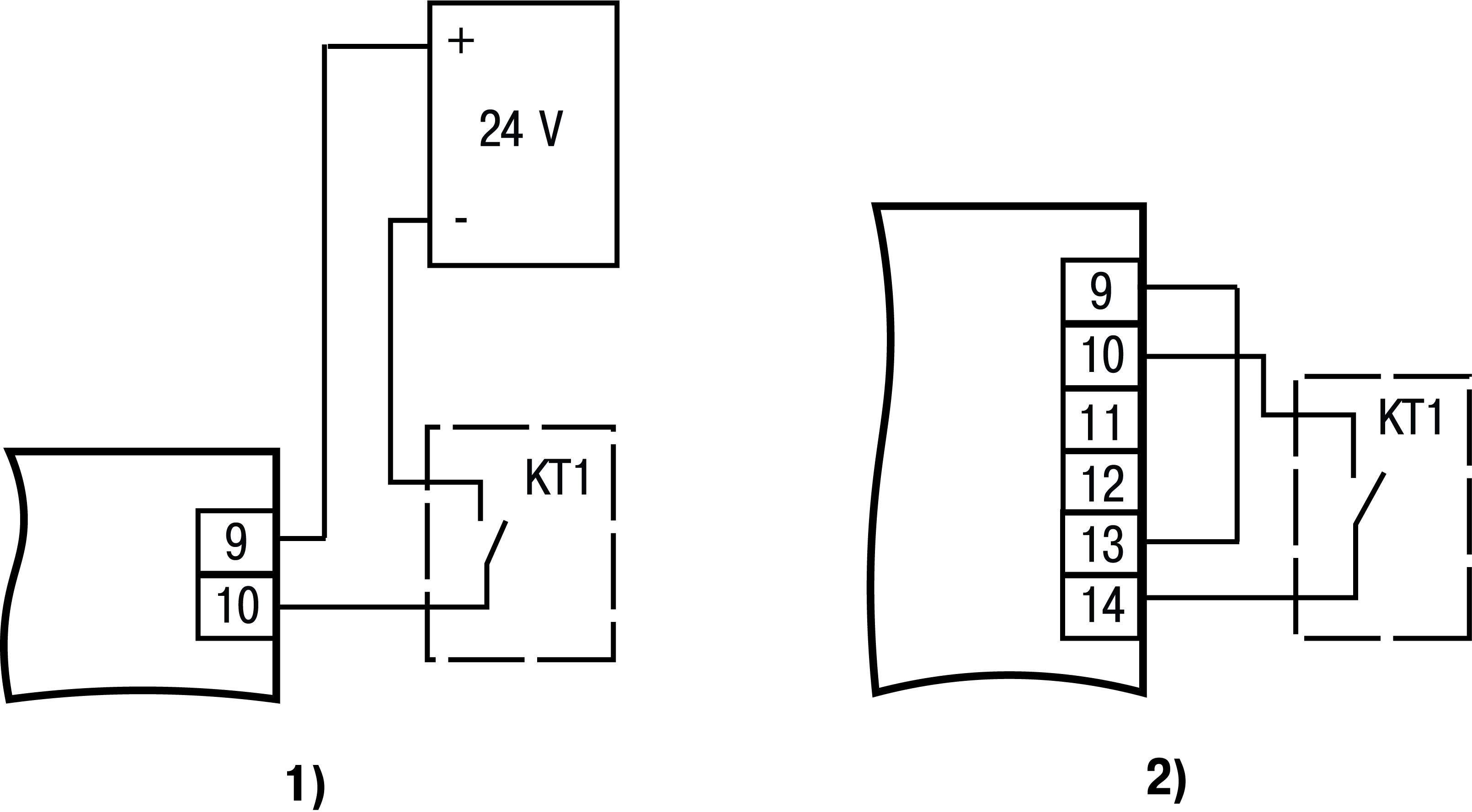
Connection of switching devices and sensors
Pin 13 is an internal power supply, required for connecting of switching devices and sensors.
If the power consumption of the input devices exceeds the load capacity of the internal power source (24 V), an external source with an output voltage of 12 to 34 V (recommended 24 V) is required.
Scheme for connection of the switching devices to the inputs is shown in Figure.
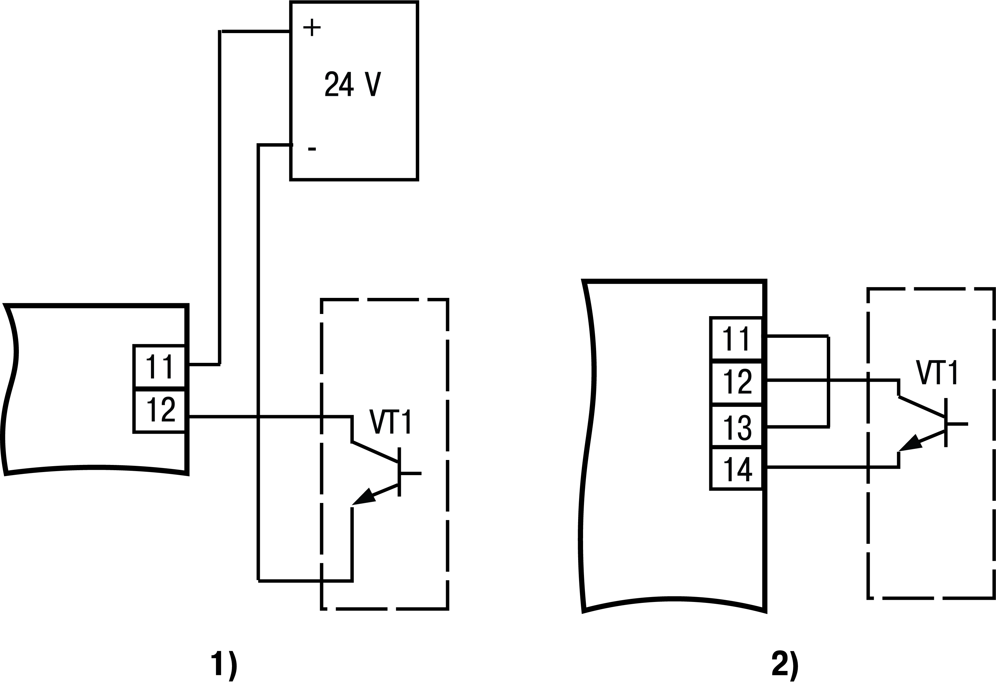
The connection diagrams of passive sensors with an n-p-n-type transistor with an open collector output are shown in Figure.
Connecting load to the outputs
The device may not have outputs, have one analog or digital output or two outputs, one of which is analog, and the second is digital.
It is possible to use an internal 24 V power supply to power the output, which is used to power active sensors.
Analog outputs
The analog output can operate as a DAC in two modes: “parameter-current” (И) or “parameter-voltage” (У).
For normal operation of devices with an analog output of type И, the DAC must be powered from an independent DC source that provides galvanic isolation of the device’s electrical circuit and “connected mechanisms”. The voltage of the power source is calculated by the formulas:
where UPS is voltage of the power source, V;
UPS min is the minimum allowable voltage of the power source, V;
UPS max is the maximum allowable voltage of the power source, V;
IDAC max is the maximum allowable current of DAC, mA;
Rload is load resistance of DAC, kΩ.
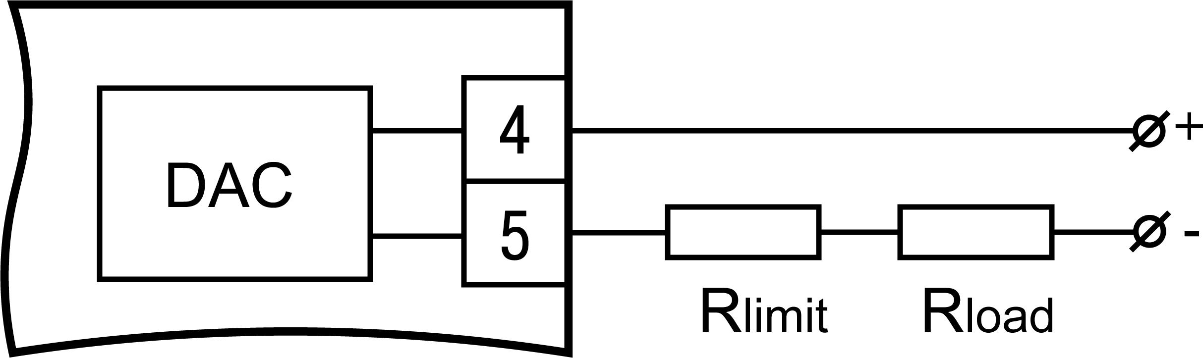
If for any reason the voltage of the DAC power supply exceeds the calculated value USP max, then the limiting resistor should be connected in series with the load, the resistance of which is calculated by the formulas:
where Rlimit nominal is nominal value of the limiting resistor, kΩ;
Rlimit min is minimum permissible value of the limiting resistor, kΩ;
Rlimit max is maximum permissible value of the limiting resistor, kΩ;
IDAC max is the maximum allowable current of DAC, mA;
UPS is voltage of the source used to power the DAC, V.
An example of the connection to the output of type И with a power source and load is presented in Figure.
An example of connection to the output of type У is shown in Figure.
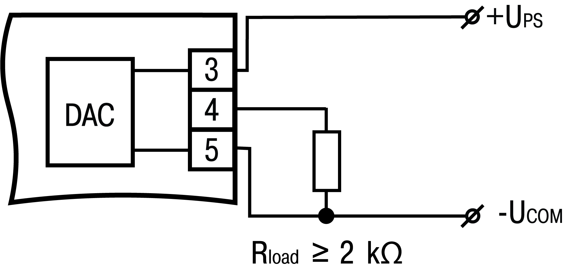
The load resistance Rload connected to the DAC must be at least 2 kΩ.
The voltage of the output power source should be not more than 30 V.
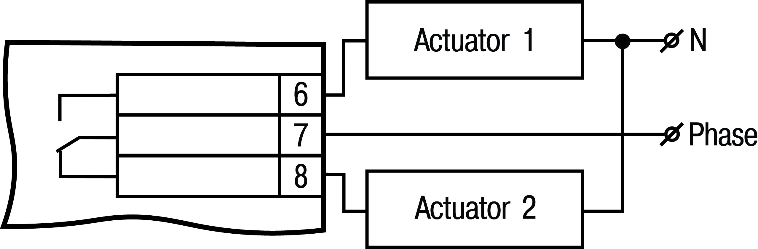
Digital output
The digital output is an electromagnetic relay (type P) (see Figure). This output is used to control the load (on / off) directly or through more powerful control elements, such as starters, solid state relays.