Setup sequence
The Setup mode is intended for viewing and editing the device parameters. New parameters are saved to non-volatile memory of the device.
To enter the setup mode, press and hold the button  for at least 2 seconds.
Using  ,
,  and
and  enter the password,
and then press and
enter the password,
and then press and  . If
the password is 0 (default), press .
. If
the password is 0 (default), press .
If no button operations are performed within 2 minutes:
- when editing a parameter, the device automatically restores its value and returns to the parameter viewing mode;
- when setting the parameter, the device automatically returns to tachometer mode.
Device settings and the possible values of each of the parameters are presented in Figures– and in Appendix.
Calibration mode setting
To enter the calibration mode, press and hold the and buttons for at least
2 seconds.
Using , and buttons enter the
password, and then press and . If the password is 0 (default), press .
To exit the menu in the parameter viewing mode, press the button .
The calibration parameters and the display of the possible values are shown in Figure.
Output settings
Device digital output (type P) functions as a comparison device (comparator).
The input value of the comparison device:
- tachometer measurement result (SrcC = tACHo) – control mode is selected using the oUtdo parameter;
- measured value of the operating time (SrcC = LiFE_T) – the output is switched on when the setpoint is reached to control the digital output for the operating time UdAY, UHour, UMin, USEc.
When the output is turned on, the ВЫХ LED lights up.
It is possible to work according to one of the following types of logic (see Figures and):
- reverse hysteresis (oUtdo = 1) – output turns on at values Fcurrent > (U+Δ) and turns off at values Fcurrent < (U-Δ);
- direct hysteresis (oUtdo = 2) – output turns on at values Fcurrent < (U-Δ) and turns off at values Fcurrent > (U+Δ);
- П-shaped logic (oUtdo = 3) – output is turned on at values (U-Δ) < Fcurrent < (U+Δ);
- U-shaped logic (oUtdo = 4) – output is turned on with the values Fcurrent < (U-Δ) and Fcurrent > (U + Δ).
- With П- or U-shaped logic, to suppress bounce during switching, there is an additional hysteresis of operation of 5 % of the range between the limits (2Δ) (see Figure).
- When the pulse repetition rate at the counting input is more than FrEQ, the value equal to the value calculated for FrEQ is set at the output.
Recommendations for setting the output:
set oFFdo = 0 and oUtdo = 0;
- specify values in Udo and dU. It is recommended that Udo, dU, the upper and lower limits do not go beyond 0 and FrEQ;
- set the desired output logic (oUtdo).
Digital output control is disabled when oUtdo = 0. The output status is set using the oFFdo parameter.
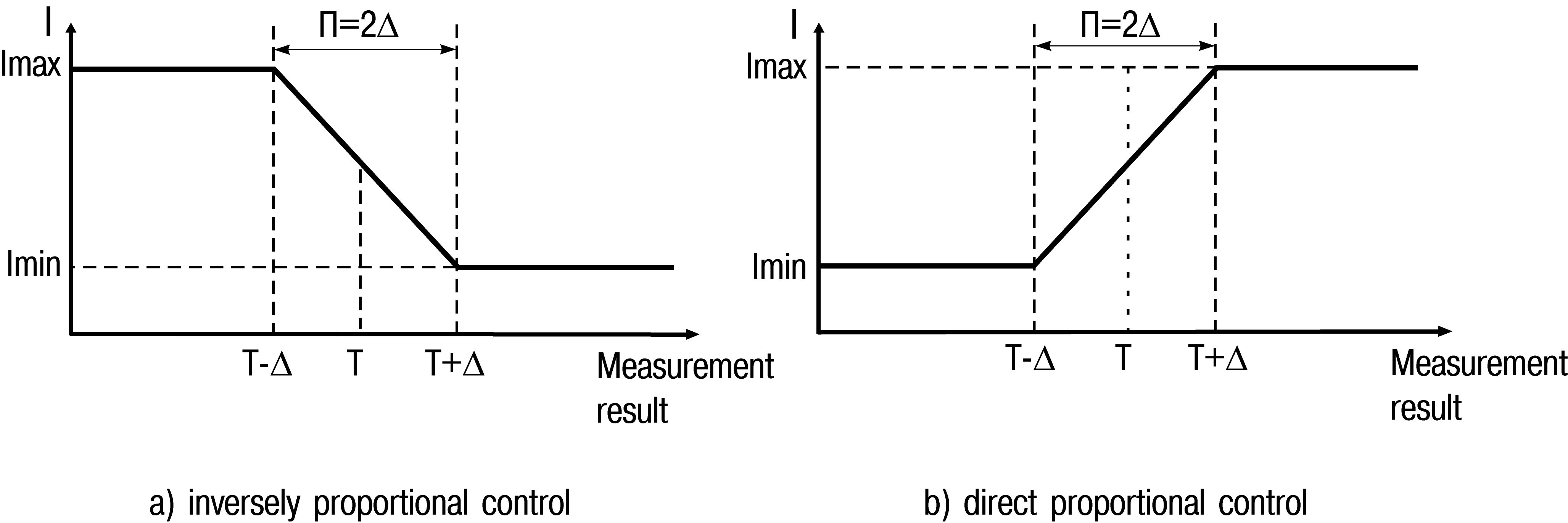
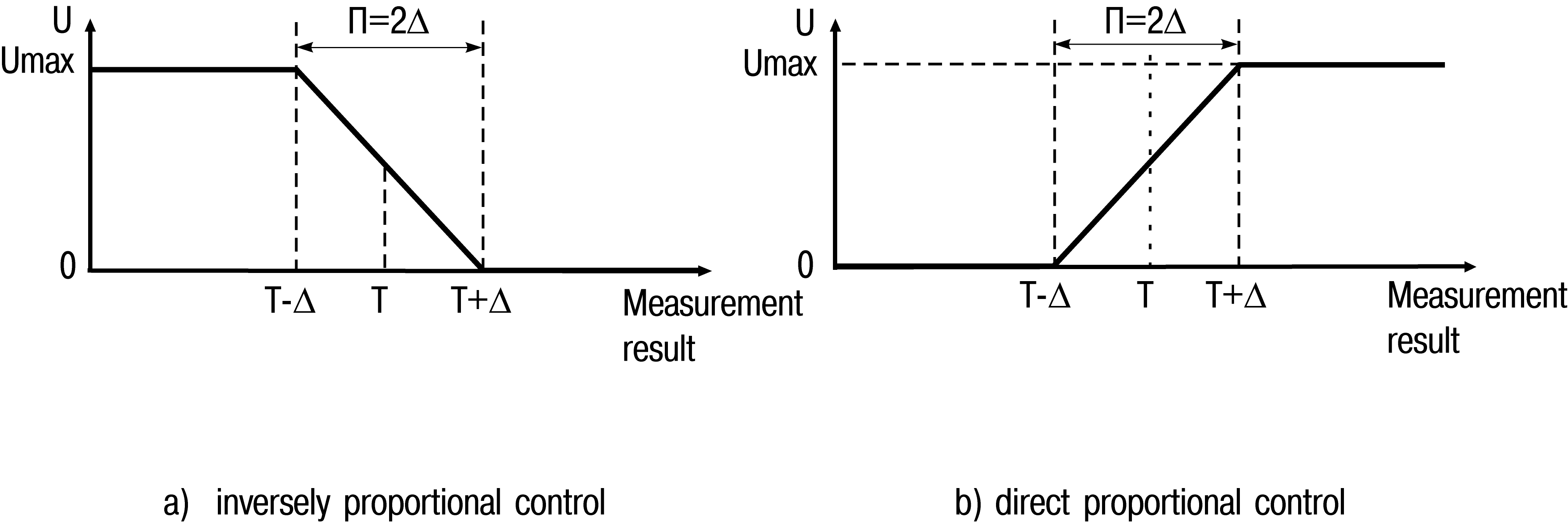
Analog output of the device (types И, У) functions as a П-controller and a recorder. The operation mode of the analog output is set using the oUtdAC parameter.
When the output operates as a П-controller, the current value of the measured value is compared with the preset setpoint (UdAC parameter) and the output signal is from 4 to 20 mA (for type И) or 0 to 10 V (for type У) proportional to the deviation. The direct proportionality zone is set by the parameter Δ (dPro). The output signal is generated in accordance with the regulator characteristic set in the oUtdAC parameter, either in direct proportion (1) or inversely proportional (2) regulation law. Graphs explaining the principle of forming the control current and voltage of the П-controller for both characteristics are shown in the Figures and.
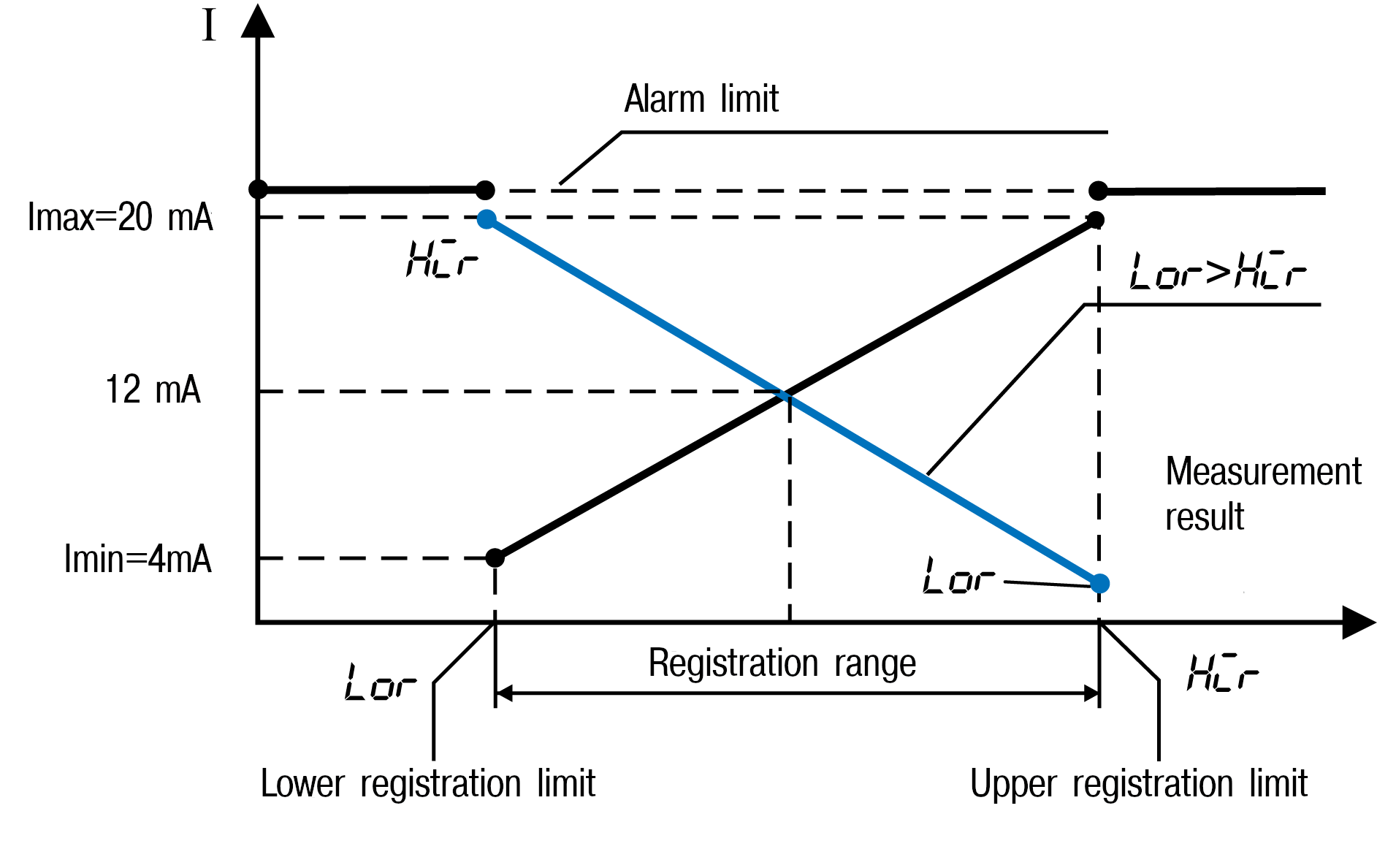
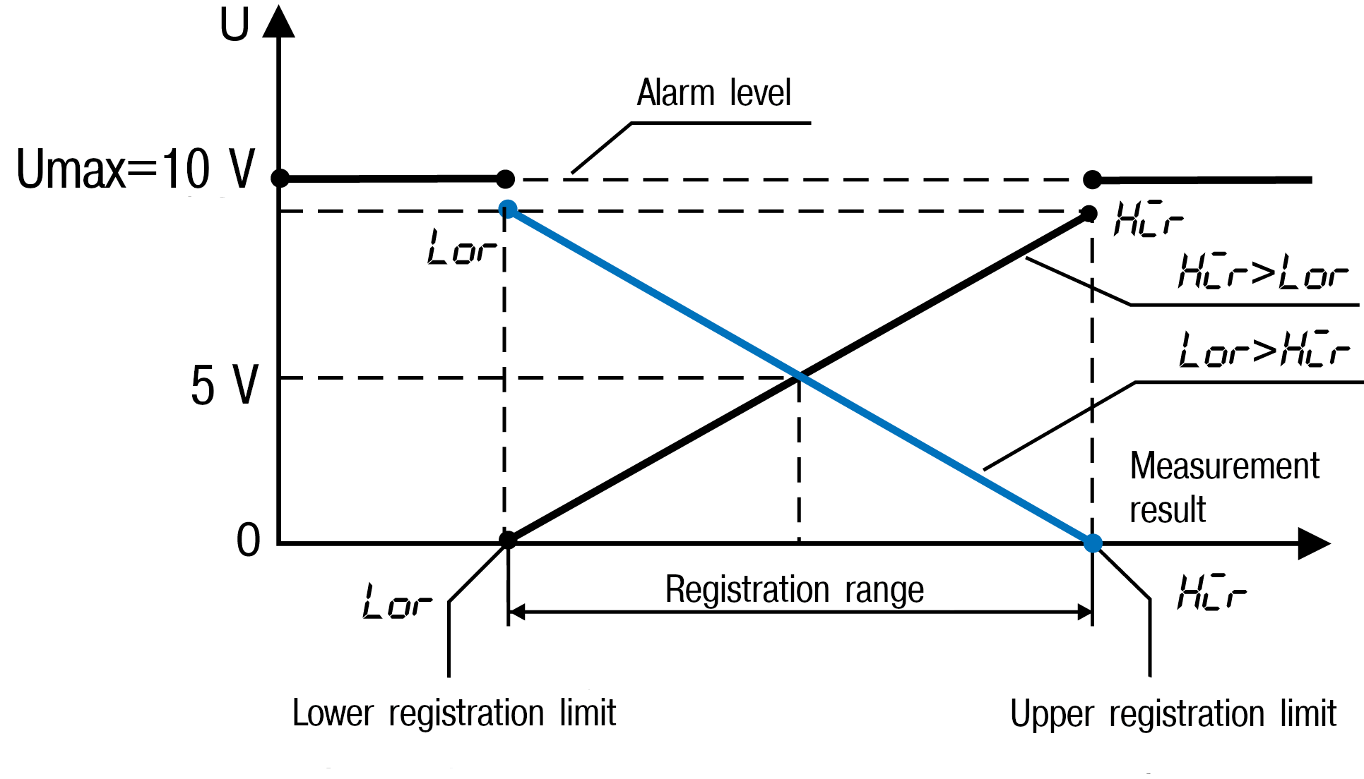
When the output works as a recorder (oUtdAC = 3), the following occurs:
- comparing the measured value with the set values of the lower limit of the recording range and the value of the entire recording range;
- issuing an analog signal to the corresponding output in the form of a current from 4 to 20 mA (for output type И) or voltage from 0 to 10 V (for output type У), which can be fed to a recorder or other recording device.
The principle of generating the output signal is shown in Figures and. When the output is working as a recorder, the lower and upper limits of registration should be set in the Lor and Hir parameters.
When oUtdAC = 0, the operation control of the analog output is disabled. The output status is set by oFFdAC parameter.
Configuring the device from a PC
To configure the device with a PC, communication interfaces RS-485 is used. The device supports two communication protocols: MODBUS RTU and MODBUS ASCII. Addresses, names and lengths of the device parameters are given in Appendix.
To go to the device settings from a PC, press and hold the and buttons for at least
2 seconds.
Then use the , and  buttons to enter the password,
and then press and . If
the password is 0 (default), press .
buttons to enter the password,
and then press and . If
the password is 0 (default), press .
To exit the menu in the parameter viewing mode, press the button .
Settings for communicating with a PC and displaying on the digital indicator the possible values of each of the parameters are presented in Figure.