This document provides detailed information about the operation principle, design, configuration, installation and maintenance of the tachometer ТХ01-RS, hereinafter referred to as the Device.
Connection, setup and maintenance should be made only by qualified specialists after reading this manual.
The device is produced in various modifications, that are encrypted in code of full conventional designation.
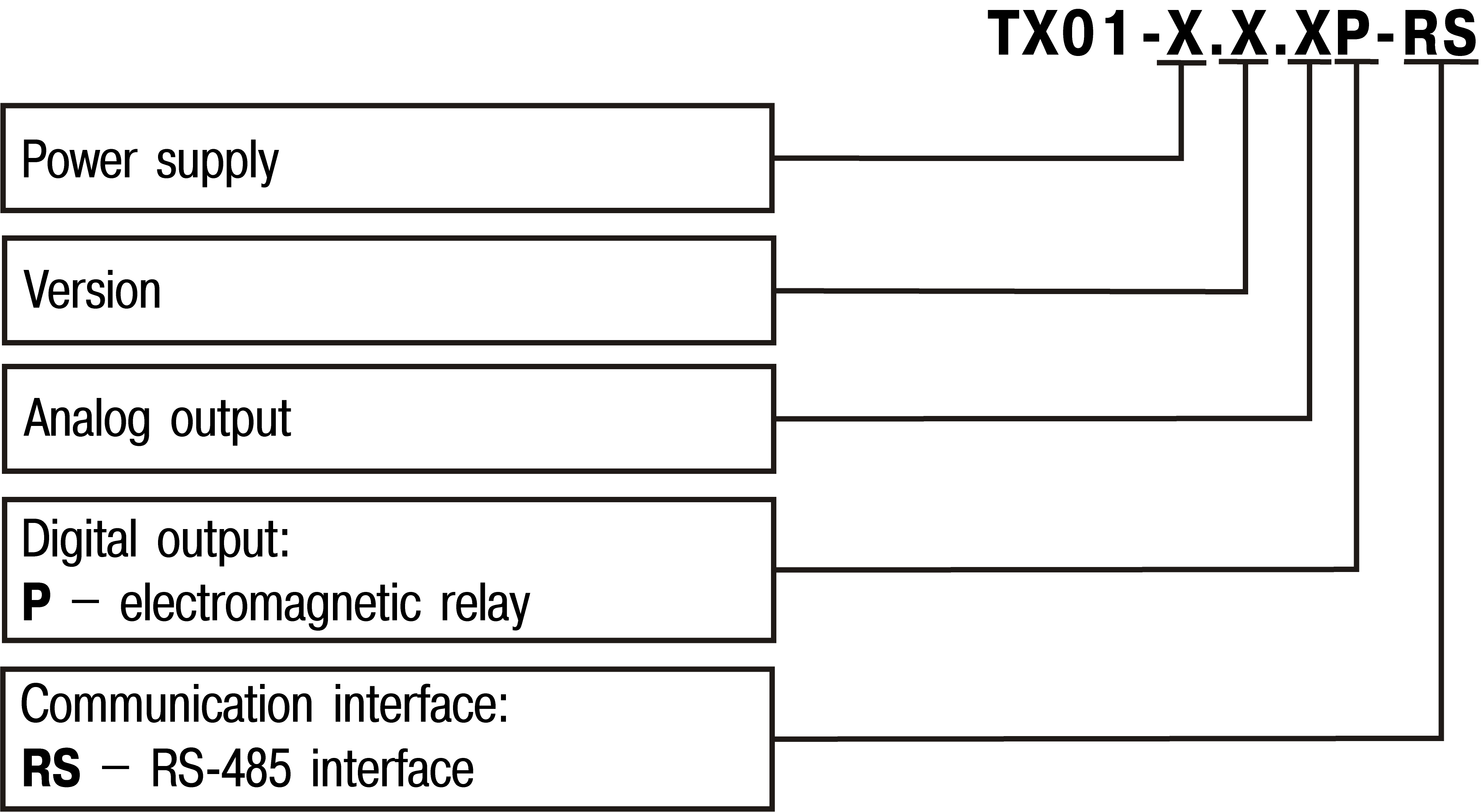
Power supply:
- 224 – 90…264 V AC or 20…34 V;
- 24 – 10,5...30 V DC.
Construction type:
- H – wall-mounting housing;
- Щ2 – panel-mounting housing.
Analog output:
- И – DAC «parameter-4…20 mA»;
- У – DAC «parameter-0…10 V»;
- not specified – without analog output
Example of ordering key: ТХ01-224.Н.ИР-RS. The device in case Н is to be delivered, with a power supply of 224 V, an analog output of type И, a discrete output of type P and an RS-485 interface.