| Network parameters |
Protocol | 0x0008 | 0 – ASCII; 1 – RTU | unsigned char | Write / Read Default – 1 |
Baud rate, bps | 0x0009 | 0 – 2400; 1 – 4800; 2 – 9600; 3 – 14400; 4 – 19200; 5 – 28800; 6 – 38400; 7 – 57600; 8 – 115200 | unsigned char | Write / Read Default – 8 |
Data word length, bits | 0x000A | 1 – 8 | unsigned char | Read Default – 1 |
Parity | 0x000C | 0 – no control (NONE); 1– parity
(EVEN); 2 – parity (ODD) | unsigned char | Write / Read Default – 0 |
Stop bits | 0x000B | 0 – 1 stop bit (1); 1 – 2 stop bits
(2) | unsigned char | Write / Read Default – 0 |
Device address | 0x0006 | from 1 to 247 | unsigned short | Write / Read Default – 16 |
Response delay, ms | 0x000D | from 0 to 45 | unsigned char | Write / Read Default – 2 |
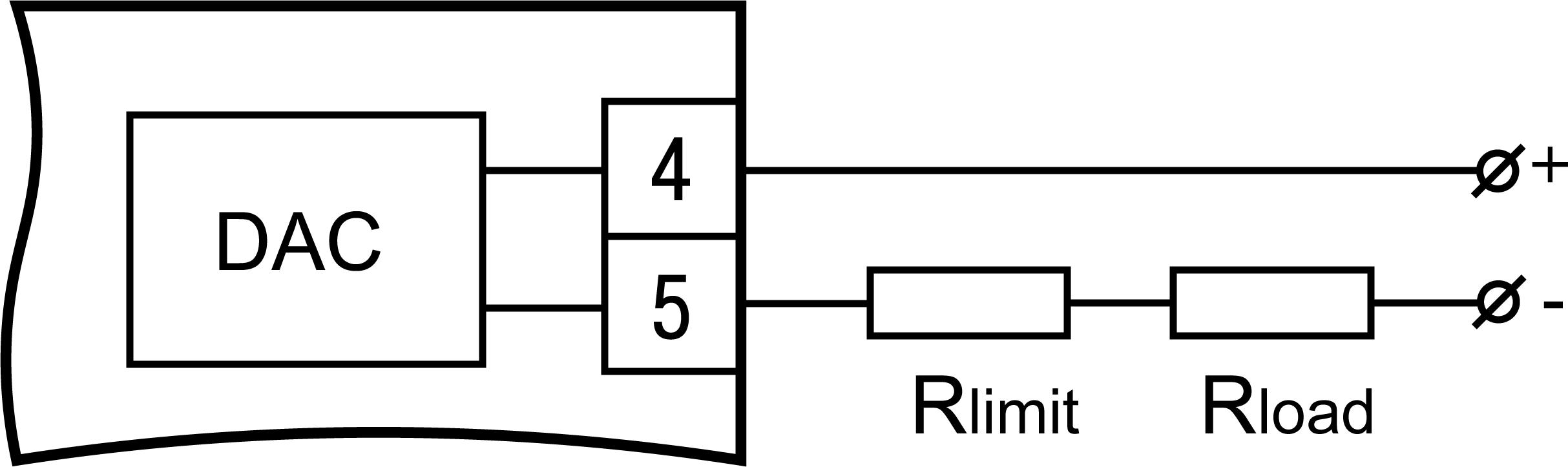
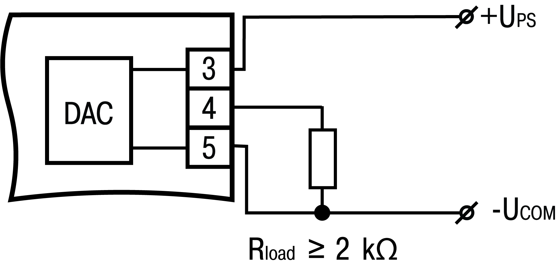
| Parameters for
devices with analog output |
Analog output mode | 0x0031 | 0 – output is off (0) 1 – directly
proportional (1); 2 – inversely proportional
(2); 3 – recorder (3) | unsigned char | Write / Read Default – 3 |
Setting value U of the analog output | 0x0032 0х0033 | from 0 to FREQ | Unsigned long | Write / Read Only for directly proportional mode. Default – 0 |
Value of the direct proportionality zone | 0x0034 0х0035 | from 1 to FREQ | Unsigned long | Write / Read Only for directly
proportional mode. Default – 1 |
Value of the lower registration limit (U-L) | 0x0036 0х0037 | from 0 to FREQ | Unsigned long | Write / Read Only in the recorder mode. Default
– 0 |
Upper registration limit value (U-H) | 0x0038 0x0039 | from 0 to FREQ | Unsigned long | Write / Read Only in the recorder mode. Default
– 2500 |
Analog output status when control is disabled | 0x003A | 0 – the value LdAC(0)
is output; 1 – the value HdAC(1) is output | unsigned char | Write / Read Default – 0 |
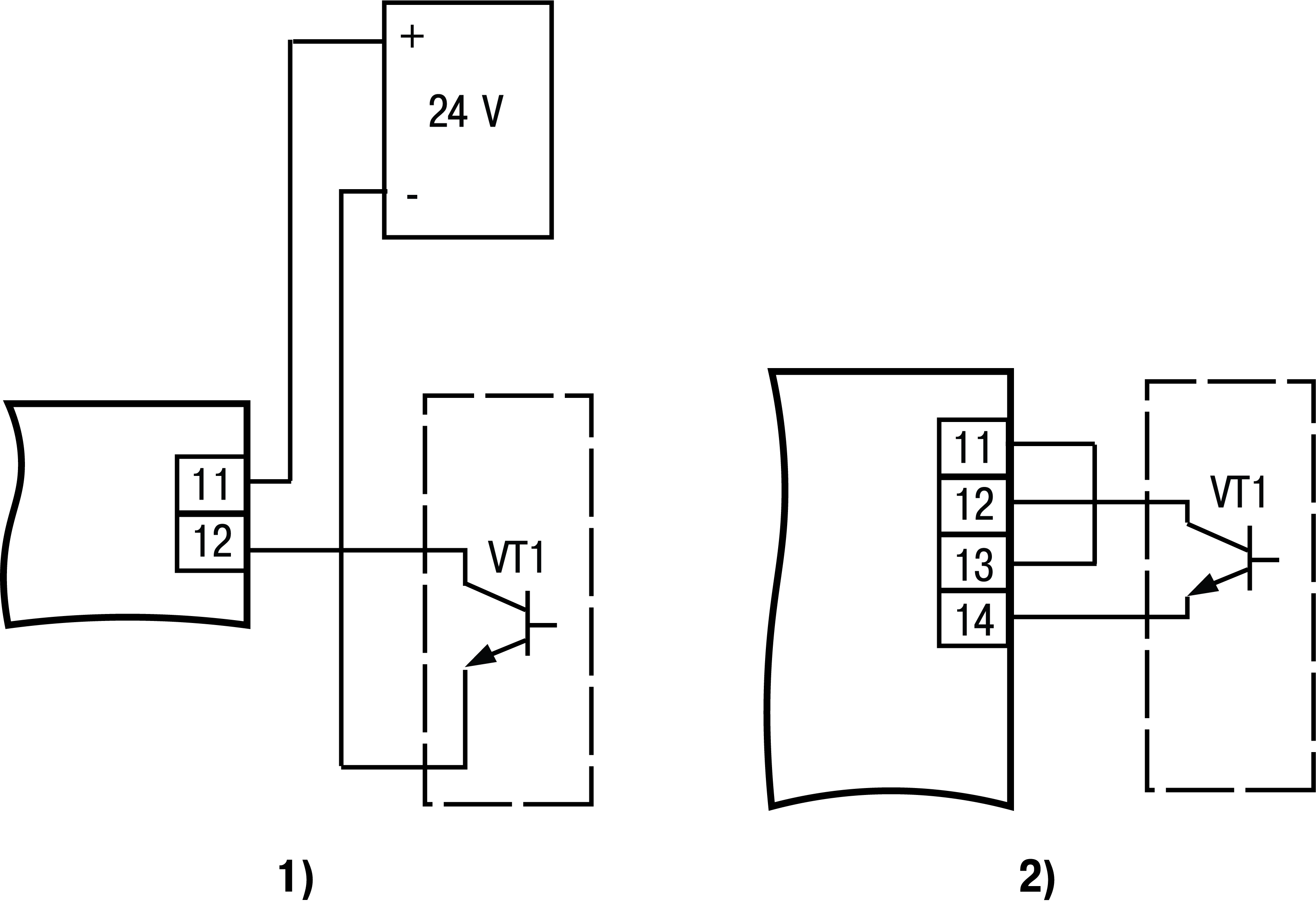
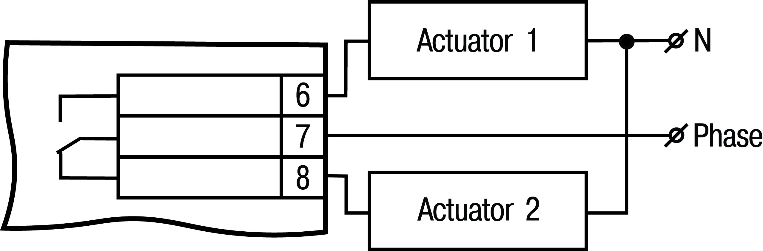
| Parameters for
devices with digital output |
Signal source for digital output | 0x0013 | 0 – tachometer measurement result (tACHo); 1 – the value HdAC(LiFE.t) is output | unsigned char | Write / Read Default – 0 |
Logic type of digital output | 0x0014 | 0 - output control is disabled (the output is transferred to the
state defined by the parameter oFFdo) (0); 1 – logic type 1 (reverse hysteresis) (1); 2 – logic type 2 (direct hysteresis) (2); 3 – logic type 3 (direct proportional) (3); 4 – logic type 4 (reverse proportional) (4); | unsigned char | Write / Read Only for input of the comparator – tachometer (SrCC = tACHo) Default
– 0 |
Digital output trigger | 0x0015 | 0 – disabled (oFF); 1 – enabled (on) | unsigned char | Write / Read Default – 0. When setting the parameter to state on, the digital
output retains its last state |
Digital output delay, s | 0x0016 | from 0 to 999 | unsigned short | Write / Read Default – 0 |
Setpoint for digital output control | 0x0017 0х0018 | from 0 to FREQ | Unsigned long | Write / Read Default – 10 at OUTDO > 0 |
Comparator hysteresis | 0x0019 0х0020 | from 0 to FREQ | Unsigned long | Write / Read Default – 1 at OUTDO > 0. The hysteresis in combination with the
setpoint must not go beyond the set limits of the device registration |
Setting value for digital output run hours control, days | 0x001B | from 0 to 9999 | unsigned short | Write / Read At SrCC = LiFE_t. Default – 0 |
Setpoint value for controlling the digital output on running
hours, h | 0x001C | from 0 to 23 | unsigned char | Write / Read At SrCC = LiFE_t. Default – 0 |
Setpoint value for control of digital output on running
hours, min | 0x001D | from 0 to 59 | unsigned char | Write / Read At SrCC = LiFE_t. Default – 0 |
Setpoint value for control of digital output on running
hours, s | 0x001E | from 0 to 59 | unsigned char | Write / Read At SrCC = LiFE_t. Default – 0 |
Digital output status when control is disabled (OUTDO = 0) | 0x001F | 0 – output is off (oFF) 1 – output is on (on) | unsigned
char | Write / Read At OUTDO = 0. Default – 0 |
Tachometer reading
| 0x0020 | 0 – rps (SEC); 1 – rpm (Min) 2 – rph (HOUR); 3 – adjustable values
(User) | unsigned char | Write / Read Default – 0 |
Tachometer reading filter | 0x0021 | from 0 to 50 s | unsigned char | Write / Read Buffer filling time of 8 values for averaging
readings. Default – 1 |
Decimal point position of device readings | 0x0022 | 0 – _ _ _ _ _ _; 1 – _ _ _ _ _._; 2 – _ _ _ _._ _; 3 – _ _ _._ _ _; 4 – _ _._ _ _ _ | unsigned char | Write / Read Default – 0 |
Multiplier decimal point position | 0x0023 | 0 – _ _ _ _ _ _; 1 – _ _ _ _ _._; 2 – _ _ _ _._ _; 3 – _ _ _._ _ _; 4 – _ _._ _ _ _ | unsigned char | Write / Read Default – 0 |
Multiplier | 0x0024 | from 1 to 999 (from 0.0001 to 999 including FDP) | unsigned short | Write / Read Default – 1 |
Maximum frequency of the input signal at the counting input,
Hz | 0x0025 0х0026 | from 1 to 2500 | Unsigned long | Write / Read Default – 2500 |
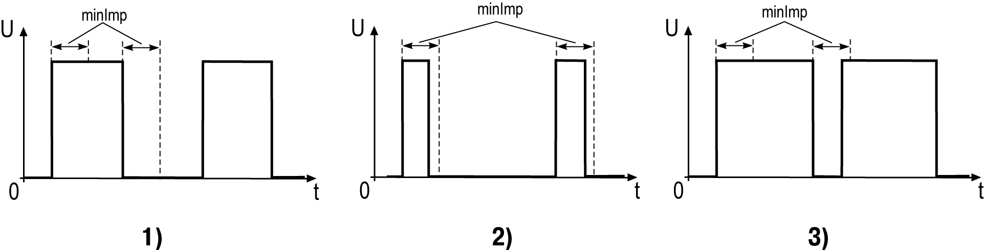
Minimum pulse duration, µs | 0х0040 0х0041 | from 10 to 999999 | Unsigned long | Write / Read Default – 10 |
Password | 0x0027 0х0028 | from 0 to 999999 | Unsigned long | Write / Read Default – 0 |
The measured value of rounds in units corresponding to the
value DTTA. Not displayed on the digital indicator | 0x0029 0х002A | from 0 to 4294967296 | Unsigned long | Read only |
Running hours, s Not displayed on the digital indicator | 0х002B 0х002C | from 0 to 863999999 | Unsigned long | Read only |
State of digital output 1 | 0x002D | 0 – output is off (oFF) 1 – output
is on (on) | unsigned char | Read only |
State of digital output 2 | 0x002E | 0 – low level (0); 1 – high level
(1) | unsigned char | Read only |
Device name | 0x0000 0x0001 0x0002 | __ТH01 | char[6] | Read only |
Firmware version | 0x0003 0x0004 0x0005 | _VХ.ХХ | char[6] | Read only |
Version of the device. Not displayed on the digital
indicator | 0x0012 | 0 – no output; 1 – only digital output; 2 –
only analog output; 3 – digital and analog outputs | unsigned char | Read only |
| Commands |
Reset running hours counter | 0x002F | 1 – reset counter (YES) | unsigned char | Write only |
Restore factory settings | 0x0030 | 1 – restore factory settings (YES) | unsigned char | Write only |
Apply network settings | 0x000F | 1 – apply settings (YES) | unsigned char | Write only New parameters take
effect after command APPLY or reboot |
| Calibration |
| The value of the code issued by the DAC to set the minimum
value of the output signal | 0x003B | from 0 to 1023 | unsigned short | Read Only in calibration mode Default – 40 |
| The value of the code issued by the DAC to set the maximum
value of the output signal | 0x003C | from 0 to 1023 | unsigned short | Read Only in calibration mode Default – 1023 |
Displacement of the lower limit of the current output | 0x003D | from -1000 to 1000 | signed short | Write only The desired offset of the DAC code relative
to the current is transmitted. Default – 0 |
Displacement of the upper limit of the current output. | 0x003E | from 1000 to -1000 | signed short | Write only The desired offset of the DAC code relative
to the current is transmitted. Default – 0 |
Apply current output calibration | 0x003F | 0 – do not apply; 1 – apply | unsigned char | Write only Default – 0 |