Wiring recommendations
To ensure the reliability of electrical connections it is recommended to use copper multicore cables, the ends of which should be carefully cleaned, tinned, otherwise use cable lugs before connection. Stripping of conductors must be performed in such way that the stripped ends after connecting to the device do not protrude beyond the terminal block. Cable cross section should be no more than 1 mm2.
General requirements for connection lines:
- During the cabling, communication lines that connect the device with sensors must be isolated to a separate circuit (or several circuits) and placed separately from power cables or other sources of high-frequency and impulse interferences.
- To protect the device inputs from the effects of industrial electromagnetic interference, the communication lines between device and sensors should be screened. Special cables with shielding or grounded steel pipes of suitable diameter can be used as screens. The cable shielding should be connected to the functional ground terminal (FE) in the control panel.
- Network interference filters should be installed in the power supply lines.
- It is necessary to install spark-suppression filters in the lines of switching of power equipment.
When mounting the system in which the device is used, the rules for effective grounding should be taken into account:
- all grounding lines must be laid in Y-connected circuit, ensuring good contact with the grounding element;
- all earthing circuits must be made with wires of the largest possible cross-section;
- it is forbidden to connect the device terminal "Common" with grounding lines.
Getting Started
If the device has been for a long time at a temperature below minus 20 °C, it is necessary to keep it in a room with a temperature corresponding to the operating range for at least 30 minutes before switching on and operation.
For connecting the device perform following actions:
-
Connect the device to a power source.
 DangerBefore powering up the device, it is necessary to check the correct connection of the supply voltage and its level.
 - Connect the "device - sensors" communication lines to the sensors and to device inputs.
- Connect the "device - load" communication lines to the actuators and to outputs of the device.
- Apply power to the device.
- Set up the device.
- Power off the device.
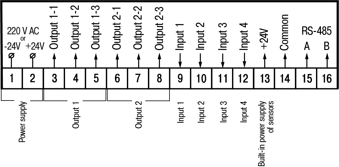
Pin assignment
Screw terminals are located on the back wall of the panel-mounting device or inside the device (wall-mounting). The terminal block contacts assignment is shown in Figure.
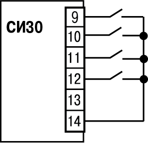
Connection of switching devices and sensors
Supply voltage on the device inputs (pins 9 – 12 at the terminal block) must be in range from 0 to 24 V.
Scheme for connection of the switching devices to the inputs is shown in Figures and .
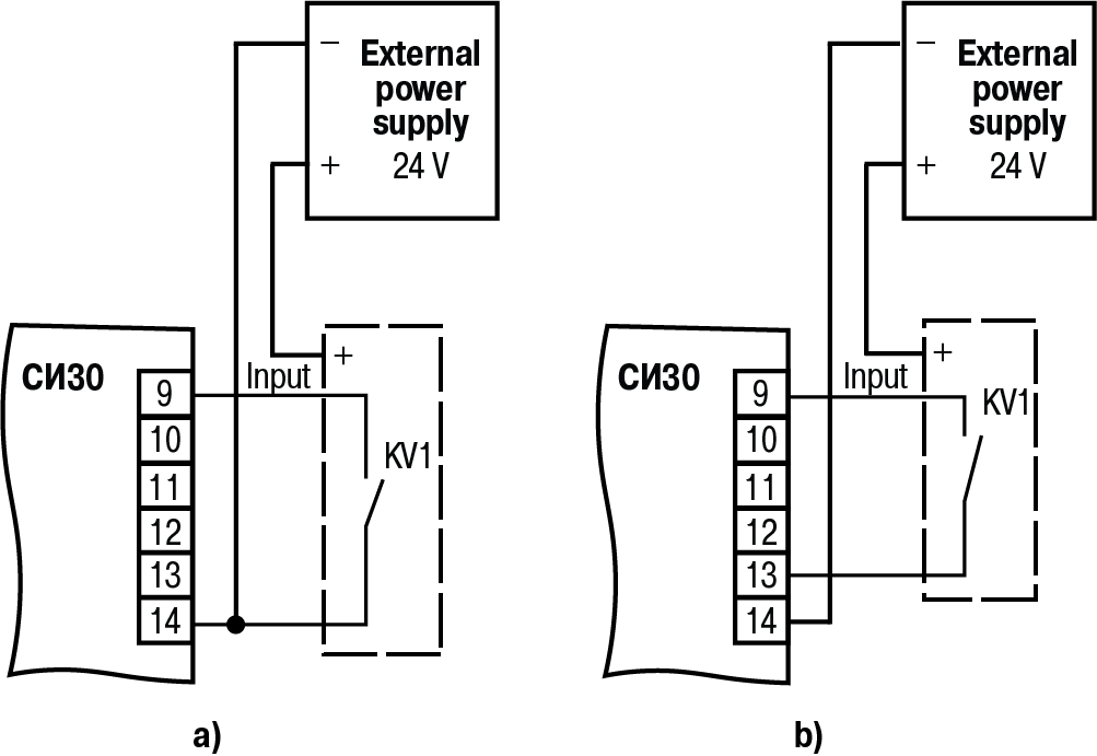
Scheme for connection of passive and active sensors with an output n-p-n open-collector transistor or p-n-p is shown in Figures and accordingly.
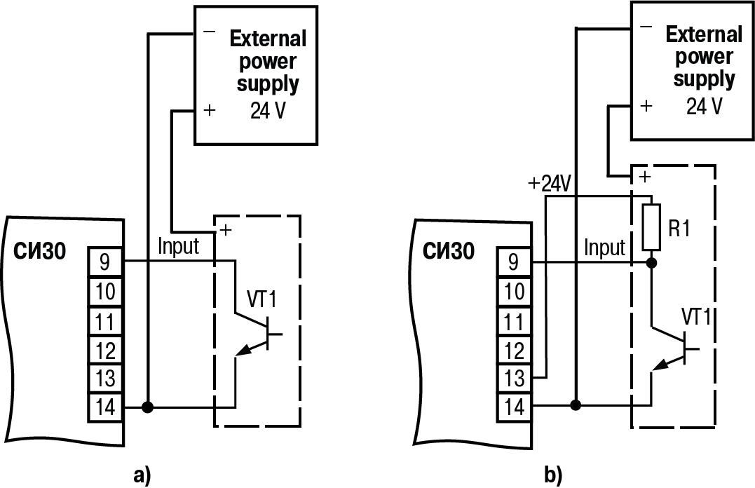
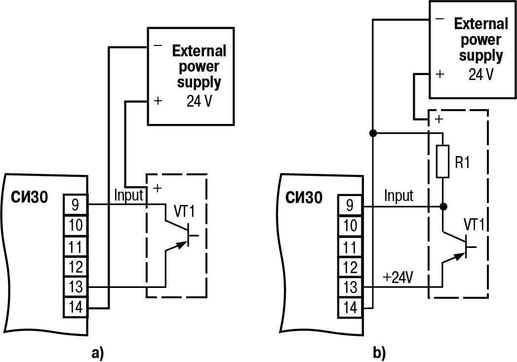
Device has a dual switch for selecting, which of the types of sensors will work. It is located on the lateral side of the housing Щ1 and Щ2. For device in the H housing, the switch is located inside the housing (to access the switch, it is necessary to remove the device cover by unscrewing the four screws that fasten the cover to the base). Appearance of the switch is shown in Figure.
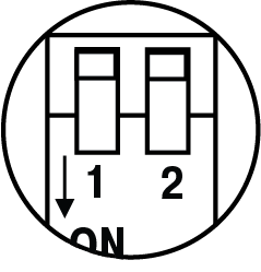
Positions of the switch depending on which device operates with different sensors, are shown in Table.
Switch status for different types of sensors
|
Type of sensors |
Switch positions |
|
n-p-n | 1 – OFF↑; 2 – ON↓ |
| p-n-p |
1 – ON↓; 2 – OFF↑ |
Connecting load to the outputs
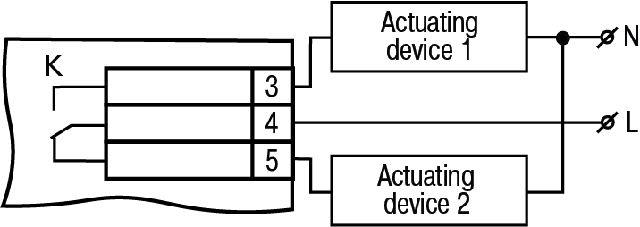
Outputs can be made in the form of electromagnetic relays (P), transistor (K) or triac (C) optocouplers. The outputs are used for direct load control (on/off) or for control by more powerful elements: contactors, solid state relays, thyristors or triacs. The outputs are galvanically isolated from the circuit of the device.
Scheme of connecting the load to the electromagnetic relay is shown in Figure.
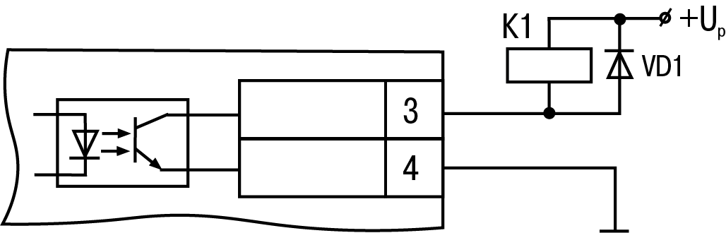
A transistor optocoupler is usually used to control a low-voltage relay (up to 50 V) – see Figure.
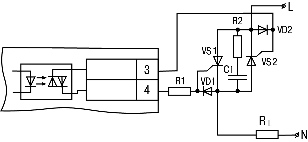
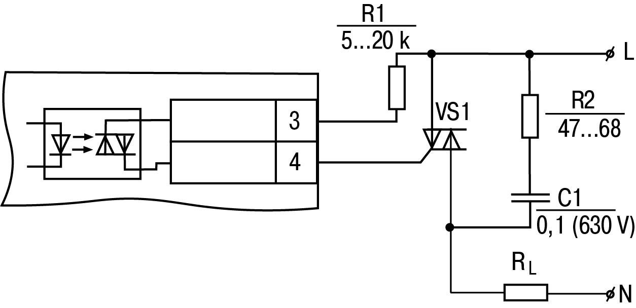
The optosimistor is connected to the control circuit of the power triac through the limiting resistor R1 according to the scheme shown in Figure.
Optosimistor can also control a pair of anti-parallel connected thyristors (see Figure).